Replace Basic Parts
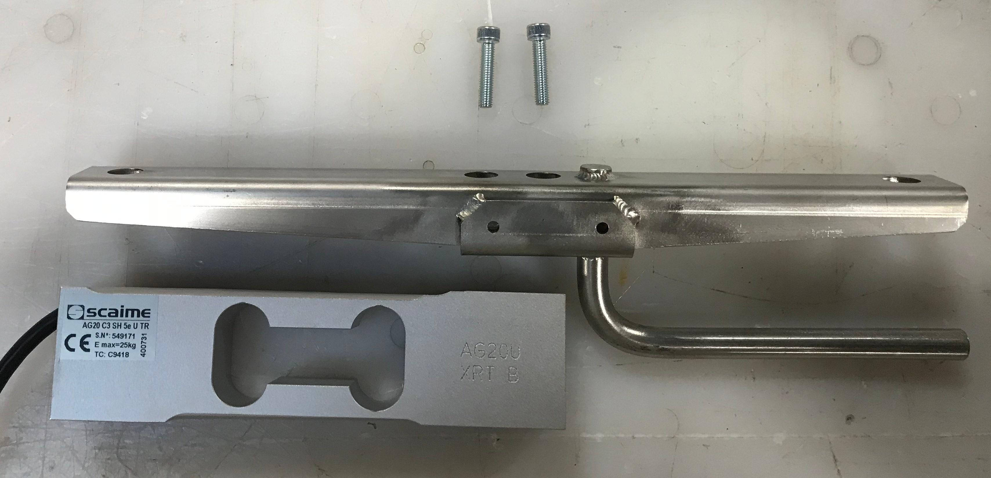
Replace the Plot Bucket Load Cell
To replace the plot bucket load cell,
- Check the voltage to locate the bad load cell.
For information on checking voltages, see Diagnostics in Mirus.
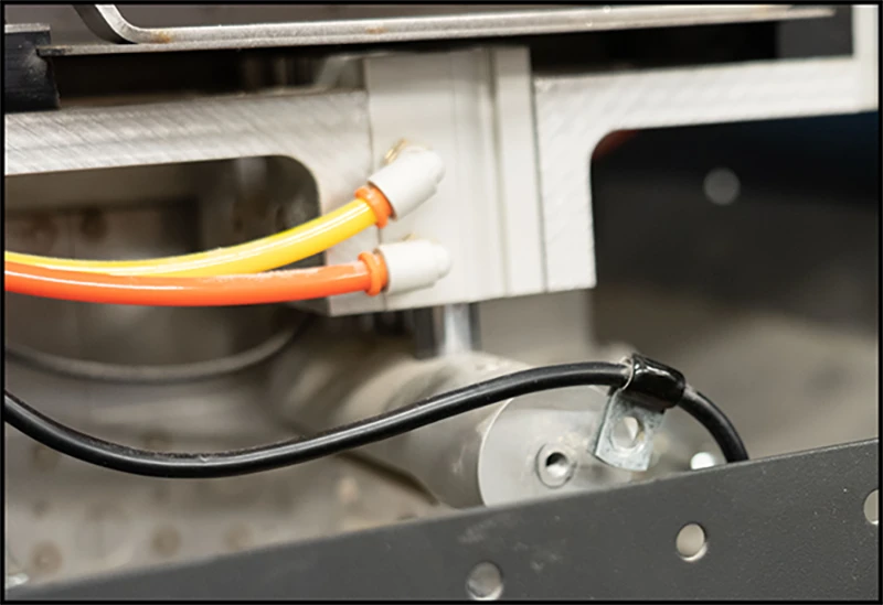
- Disconnect the cord from the bad load cell.
- Clip the zip ties holding the load cell cords.
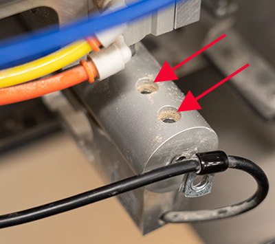
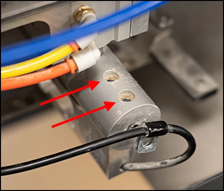
- Use a 3/16 Allen wrench to remove the two cap screws from the bottom side of the load cell.
- Lift the bucket out of the track and remove the entire load cell assembly from the GrainGage.
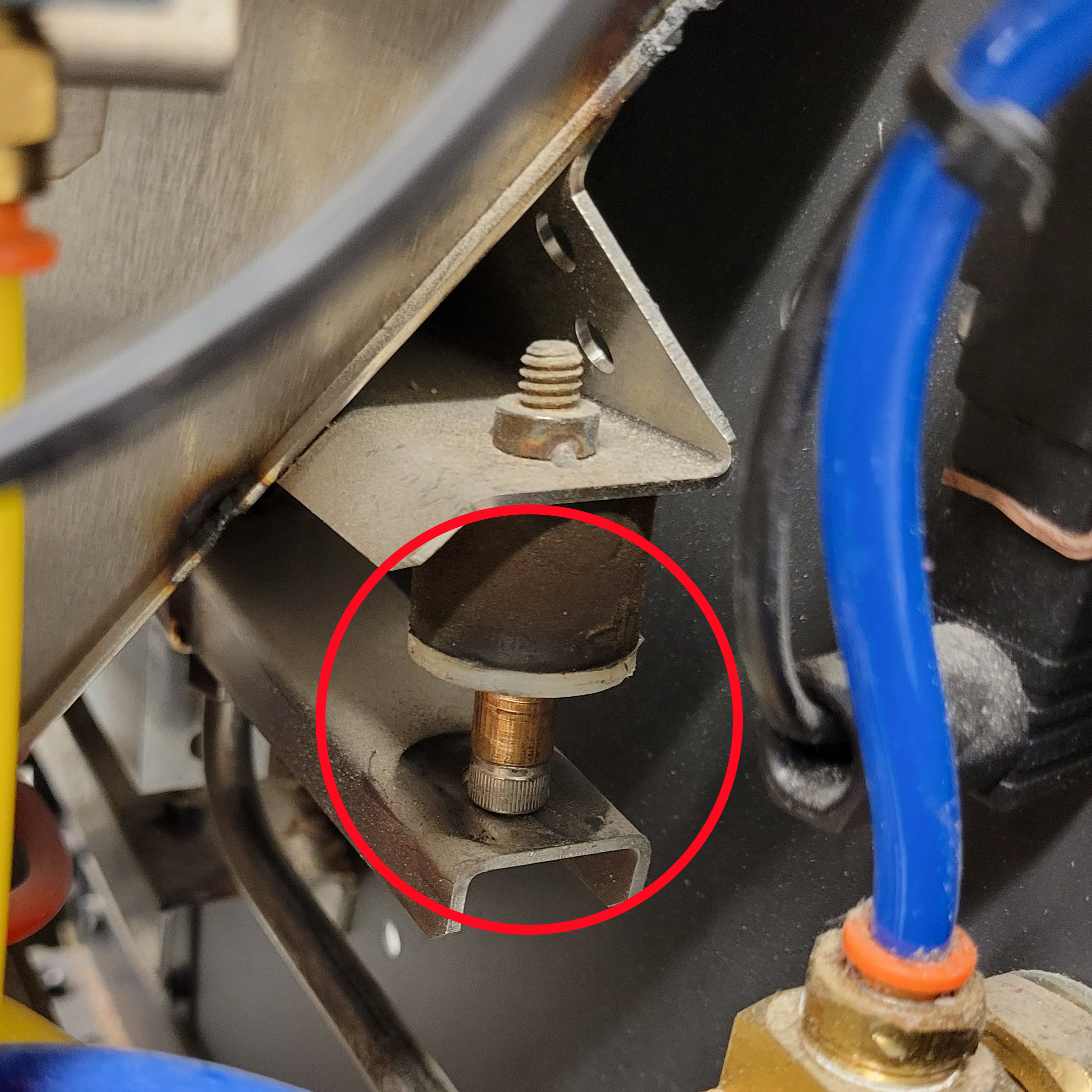
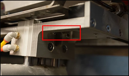
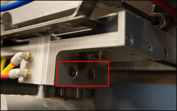
- Remove the two cap screws from the top side of the bucket track with the 3/16 Allen wrench.
- Replace the bad load cell with the new load cell. Tighten the cap screws from the top of the bucket track. Ensure the track and load cell are aligned.
- Lift the bucket out of the way to place your load cell assembly back into place. Tighten the cap screws into the bottom of the load cell. Ensure everything is aligned and the bucket is back in the track.
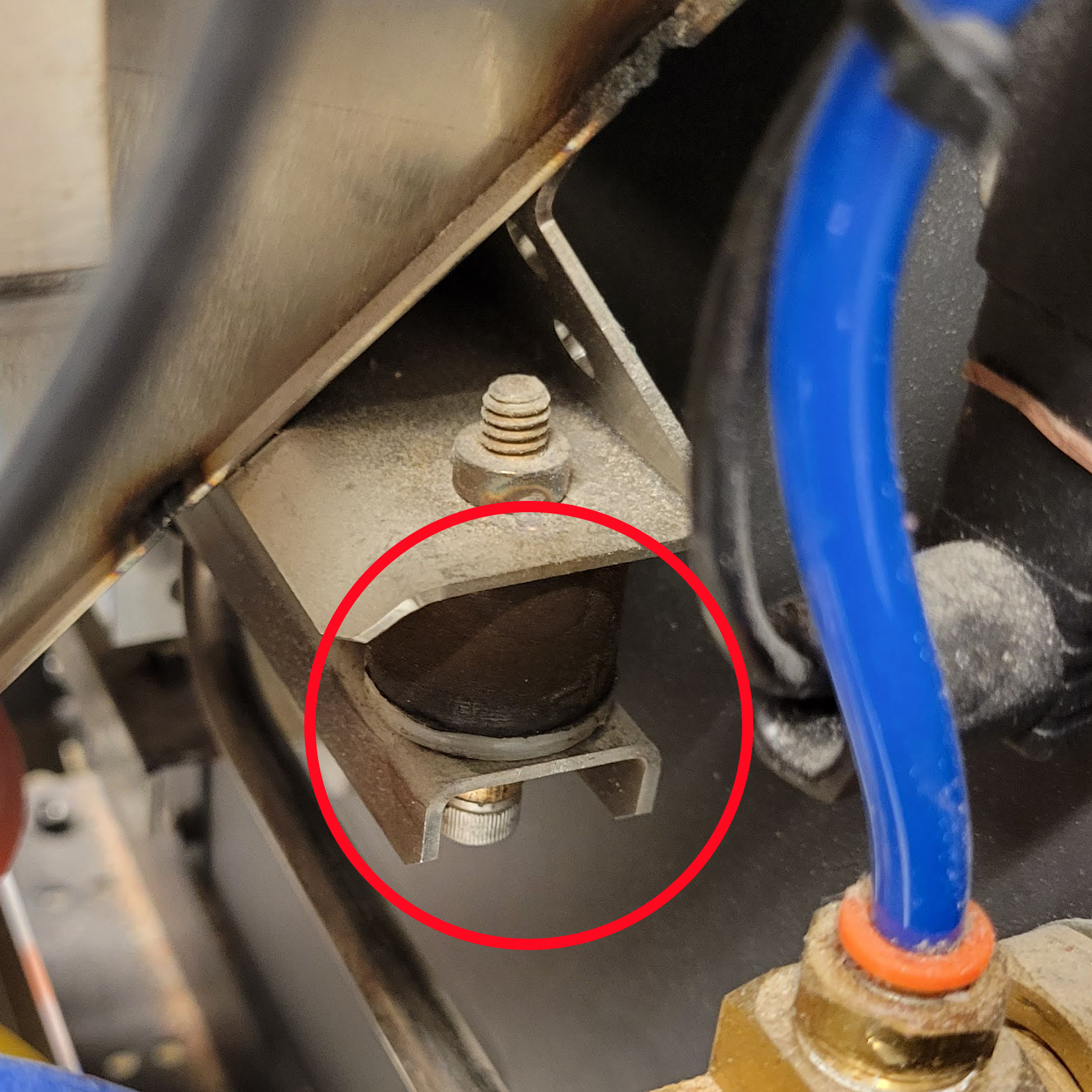
- Use a 7/64 Allen wrench to set your overload protection screw, so it is snug on the .010 feeler gauge.
- Use zip ties to secure the wires out of the way. Clip off the end of the zip ties.
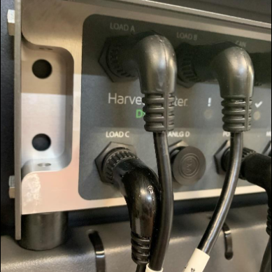
- Plug the load cell cord into the port in step 2 to connect your new load cell to the DSP module.
- After you replace a load cell, re-calibrate the weigh bucket. (Refer to the Mirus for H2/H3 Classic GrainGage User Guide)
If you have any questions about how to replace the plot bucket load cell, contact a HarvestMaster Field Service Engineer.
Replace the Test Weight Load Cell
To replace the test weight load cell,
- Use a 3/16 Allen wrench to remove the socket cap screw holding the load cell cable to the separator cylinder.
- Use the same wrench to remove the two socket cap screws holding the separator cylinder and load cell together.
- Turn off the GrainGage air and manually slide open the bottom gate.
- For the H3 Classic GrainGage, remove the SCiO Sensor.
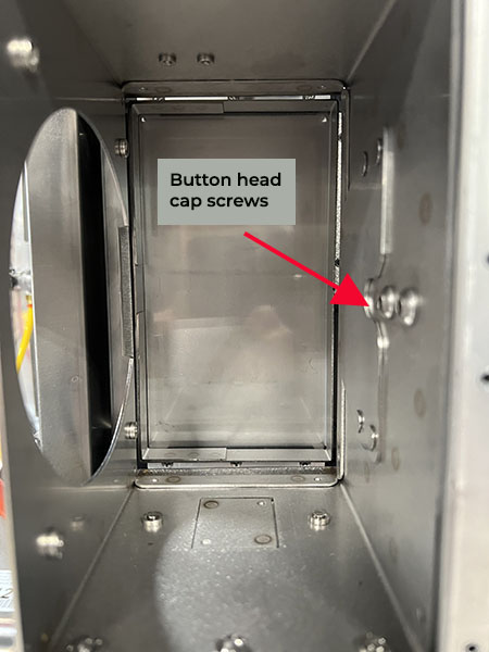
- While supporting the test weight chamber, use a 5/32 Allen wrench to remove the two button head screws from the inside of the test weight chamber.
![]() CAUTION: Be careful not to round the screws. Clean the dirt from the head of the screws. If they are locked too tight, heat the screws with a small blow torch to loosen the Loctite®.
CAUTION: Be careful not to round the screws. Clean the dirt from the head of the screws. If they are locked too tight, heat the screws with a small blow torch to loosen the Loctite®.
Note: The test weight chamber is now loose and must be supported with your hand or a zip tie.
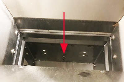
- Cut the zip ties that route the load cell cable to the DSP module.
- Remove the load cell from the system.
- To install the new load cell, replace the screws in the exact opposite order that you removed them (in steps 1–4).
- Apply Loctite 243 to the threads of the two button head screws. Hand tighten the screws.
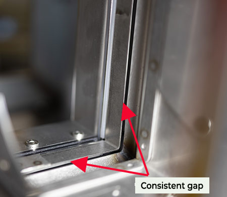
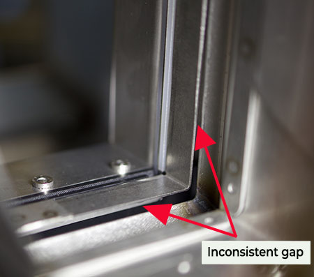
- Check that new chamber is properly aligned.
- The gap between the field guide and the chamber is even and consistent. Check the gap when the chamber is in the down position.
- The chamber slides freely. It does not rub or bump.
- Tighten the button head screws securely.
![]() CAUTION: Make sure the test chamber can slide up and down freely without contacting the fill guide.
CAUTION: Make sure the test chamber can slide up and down freely without contacting the fill guide.
Note: It is possible to install the test chamber crooked enough that it will hit the fill guide when it raises. Lightly tighten the test chamber screws, ensure proper alignment, and then tighten the test chamber screws completely.
- Route the load cell cable to the module as it was routed on the previous load cell.
- Locate the two overload protection screws.
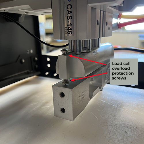
- Adjust the overload stops to the following specifications:
- Top screw: -0.009 in. gap
- Bottom screw: 0.014 in. gap
- Recalibrate the test weight load cell as outlined in the Mirus for H2/H3 Classic GrainGage User Guide.
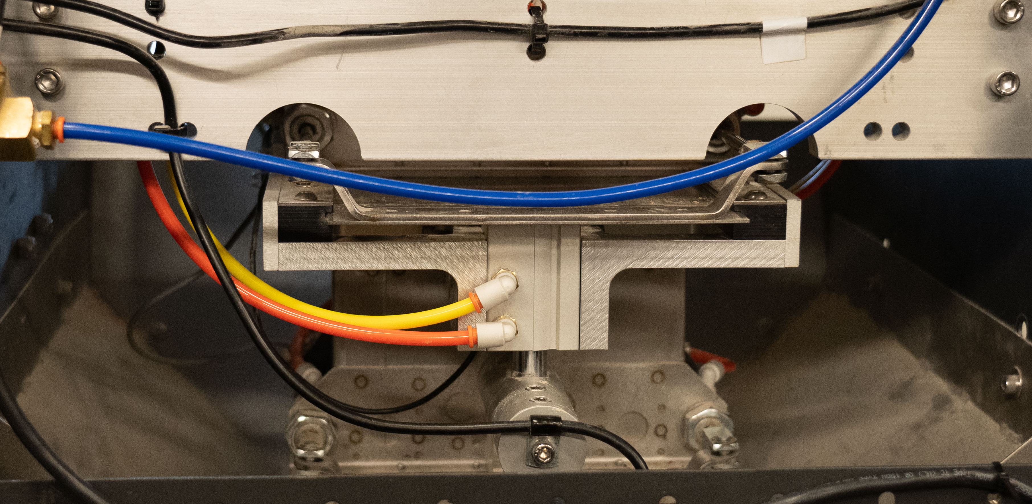
Replace the Solenoid
To replace the solenoid,
- Turn off the air and power to the GrainGage.
- Disconnect the airlines from the solenoid. Note the location of each color.
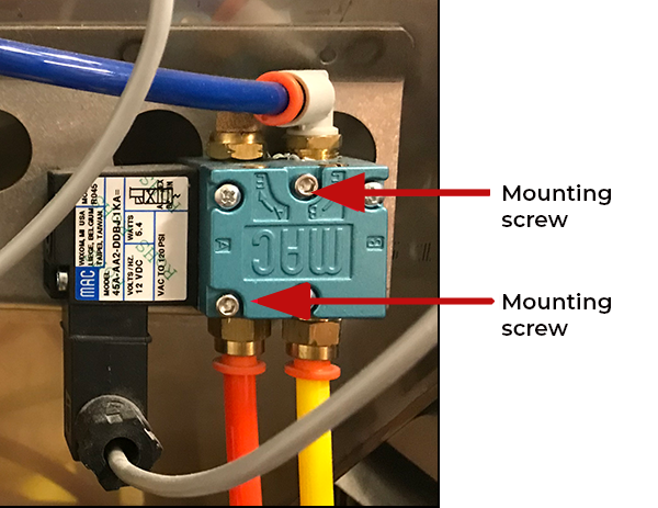
- Remove the mounting screws with a 7/64 Allen wrench.
- Disconnect the cable by removing the cable screw underneath the black cable box and unplugging the cable.
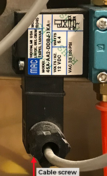
- Screw the black cable box onto the new solenoid.
- Screw the new solenoid in place with the mounting screws.
- Reconnect the airlines.
- Turn on the air and power to the GrainGage.
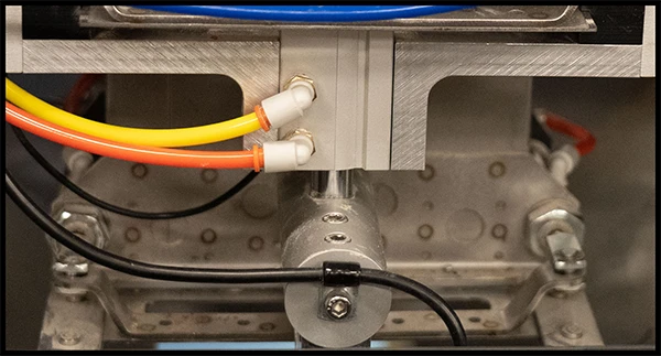
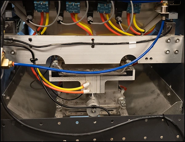
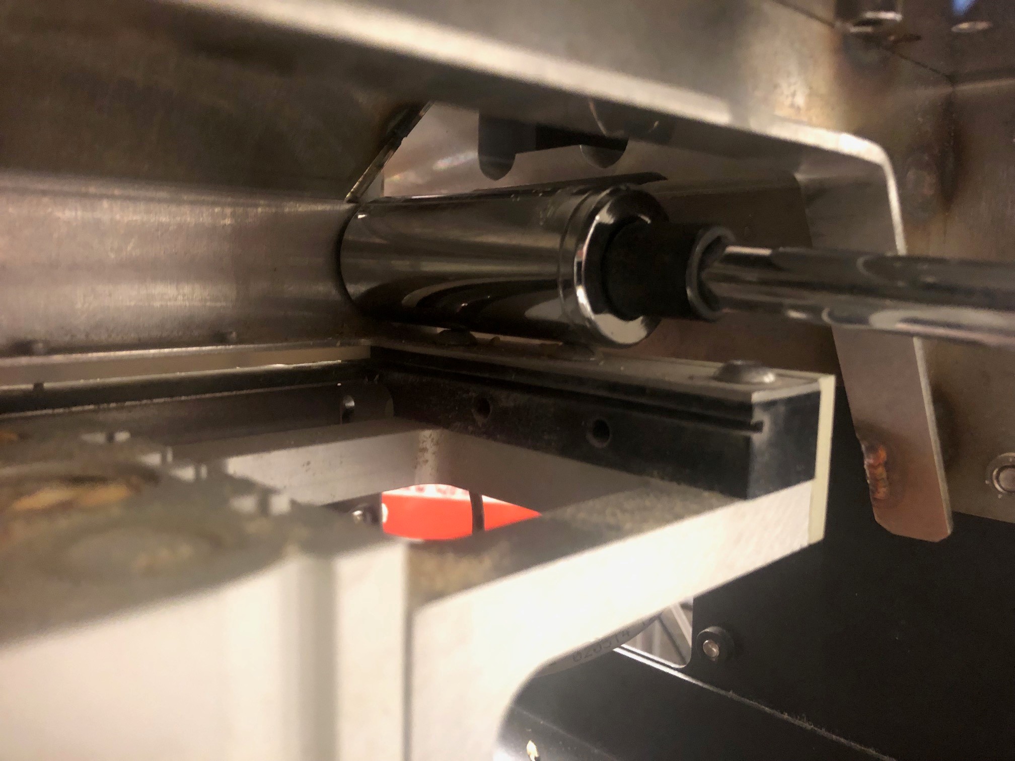
Replace the Test Weight Separator Cylinder
Remove the Faulty Cylinder
To remove the faulty test weight separator cylinder,
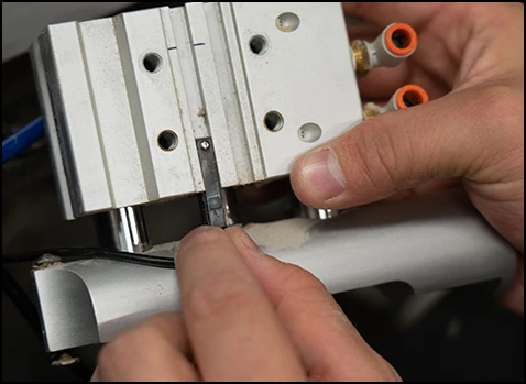
- Remove the load cell wire support socket cap screw with the 3/16 Allen wrench.
- Remove the socket cap screws that attach the load cell to the support arm.
Note: The test weight chamber will drop down when the load cell socket cap screw is removed. Support the test weight chamber so that it does not hang on the load cell and limit switch wires.
- Remove the two socket cap screws on either side of the separator cylinder supports with the 3/16 Allen wrench.
- If the bracket has two countersunk Allen screw on each side of the separator, remove the screws with the 5/32 Allen wrench.
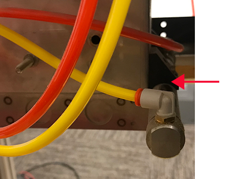
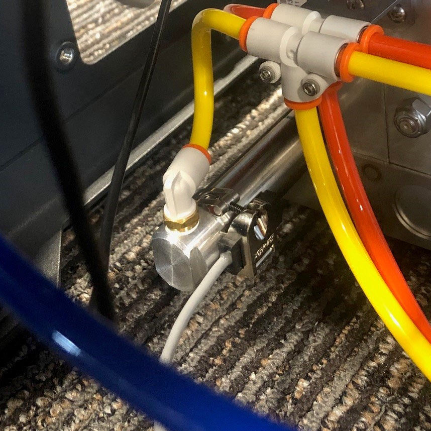
- Detach the air hoses by compressing the orange collar and pulling out the hose. Note the location of each color.

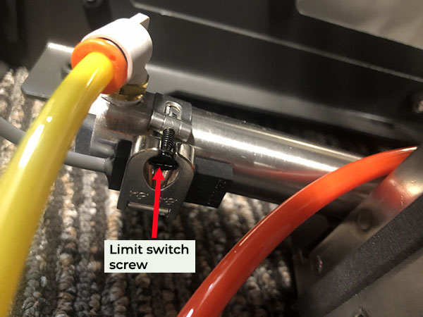
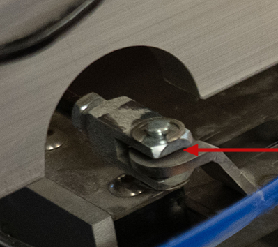
- Lower the separator cylinder from the supports and loosen the limit switch sensor with the small 1.8 mm flathead screwdriver. Extend the separator cylinder to fully release the sensor from the cylinder.
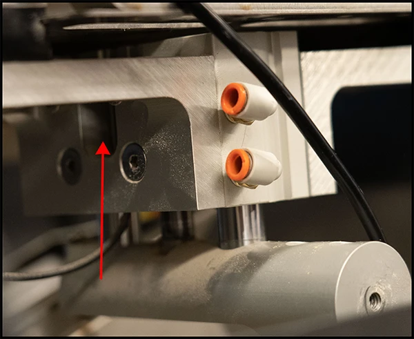
Note: Pay attention to the orientation of the limit switch sensor, including which side the sensor is on and which channel the sensor is in.
Install the New Cylinder
To install the new separator cylinder,
- Turn on the GrainGage console.
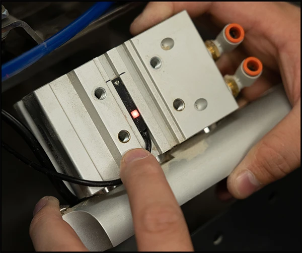
- Extend the new separator cylinder and slide the limit switch into the channel.
- Retract the separator cylinder.
With the GrainGage power on, the red LED will light up when sliding the sensor up and down in the channel.
- Put the sensor in the middle of the lit-up range and tighten securely with the small flathead screwdriver.
- Apply medium strength Loctite to all four threaded holes on both sides of the separator cylinder.
- Raise the separator cylinder carefully between the support brackets from the bottom of the brackets up.
- Replace the two socket cap screws on each side of the separator cylinder.
- Replace the two countersunk Allen screws on each side of the separator cylinder.
Note: Tighten the countersunk Allen screws before tightening the socket cap screws to align the separator into place.
- Apply non-permanent Loctite to the two threaded holes in the top of the load cell and raise the test weight chamber back into place. It may take a little work to get the weight chamber into place on top of the overload protection screws in the load cell support arm.
- Replace the two socket cap screws through the support arm into the load cell and tighten.
- Apply medium strength Loctite to the threaded hole at the end of the load cell support arm.
- Reattach the load cell wire support hanger with the socket cap screw.
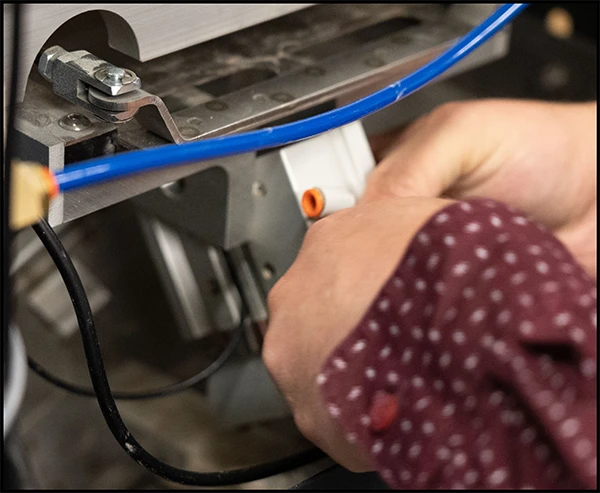
- Reattach the air hoses.
- Adjust the overload protection screws, using the 5/16 wrench with the feeler gauge to a .009 gap on the top of the overload screw followed by a .014 gap on the bottom overload screw by the load cell.
- Verify that the new separator cylinder operates smoothly.
Replace the Gate Air Cylinders
To replace the gate air cylinders,
- Turn off the air and power.
- Disconnect the airlines to the desired cylinder. Note the location of each color.
- Remove the screw on the limit switch and mounting bracket. Set the screw aside.
- Remove the snap ring and retaining pin that separates both cylinders. Remove the slide gate.
- From the open access panel, hold the nut with a 7/16 wrench and use another 1/2 wrench to remove the clevis from the cylinder rod.
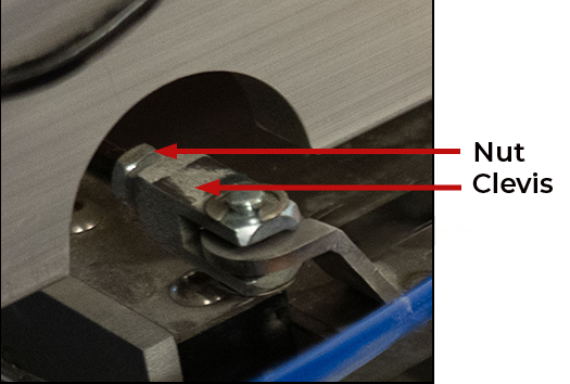
- Remove the remaining nuts with the 7/16 wrench.
- Remove and discard any black retainer blocks from the cylinder. Plug the hole with a shorter bolt.
- Use a 5/8 wrench to hold the back of the cylinder while using a 5/16 deep socket and extension to remove the large nut securing the cylinder.
- Remove the cylinder.
- Remove the NPT fittings (air fittings) from the old cylinder and install the fittings on the new cylinder. Use Teflon tape to seal the threads.
- Install the two 1/4 inch nuts and clevis on the new cylinder rod. Tighten the nuts to the end of the threads on the rod.
- Slide in the new cylinder and position it so that the air inlet/outlet matches the position of the old cylinder.
- Tighten the larger nut on the new cylinder with a 15/16 socket and extension while holding the back of the cylinder with 5/8 wrench.
- Reinstall the slide gate.
- Return the snap ring and retaining pin.
- Replace the access panel.
- Reinstall the limit switch.
- Adjust the limit gate cylinder limit switches. (See Adjust the Bottom Gate Limit Switch.)
- Reconnect the airlines and turn on the power and air to the GrainGage.
Upgrade to SCiO NIR Sensor (H2 Only)
With the H2 NIR Upgrade Kit, you can replace the EM moisture sensor with an NIR sensor and convert an H2 GrainGage to an H3 with a few simple modifications. For instructions on upgrading to the NIR sensor, see H2 NIR Upgrade Installation Guide.