Introduction
The H2 and H3 Single GrainGages provide highly accurate measurements for plot weight, moisture, test weight, and more during the harvest of large plot, high-volume grain samples. In addition to these features, the H3 Single GrainGage uses world-class SCiO™ near infrared (NIR) spectroscopy for certain grains and includes ready-to-use calibrations for many crops.
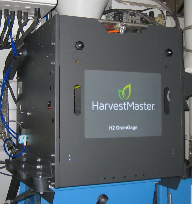
The GrainGage controls the flow of harvested material through the measurement system and compensates for slope and motion to produce results similar to those on a stationary, level platform. The heart of the GrainGage is the DSP (Digital Signal Processing) electronics module, which handles the bulk of logic, communications, and control in the GrainGage.
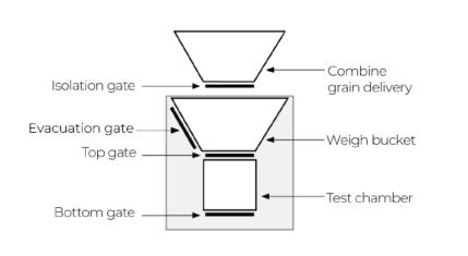
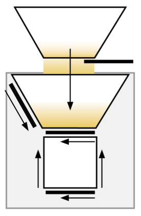
Illustration of the Single GrainGage System
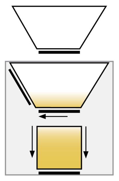
The GrainGage uses a batch-measurement system, which automatically detects when to cycle based on the weight trip point. The number of cycles per plot is determined by the amount of harvested grain.
The basic process is outlined below:
| Single GrainGage System | ||
| Step |
Description |
Diagram |
|
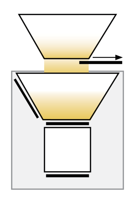
The isolation gate opens. Grain falls into the weigh bucket as its harvested until a cycle is initiated either by the operator (flush cycle) or by the GrainGage when the weight trip point is met. |
 |
|
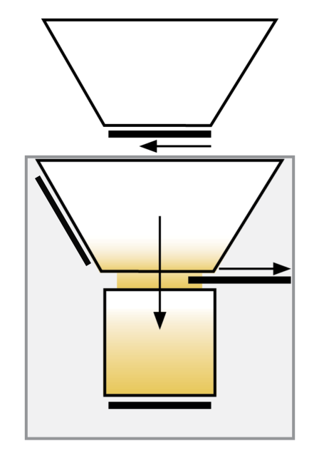
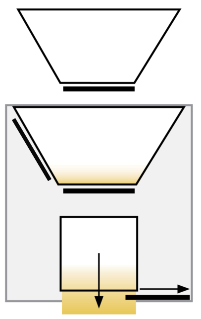
The isolation gate closes. If the amount of harvested grain is above the minimum weight threshold, the top gate opens. The test chamber fills with grain from the weigh bucket. If the amount of harvested grain is below the minimum weight threshold, the sample is weighed, but no test weight, moisture, or NIR constituent data is taken. The sample is evacuated. |
 |
|
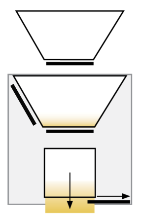
The top gate closes. Test chamber drops and separates from the weigh bucket. The GrainGage measures total bucket weight, test weight, moisture, and constituent NIR data. |
 |
|
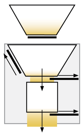
The bottom gate opens, emptying the test chamber. If the harvested material meets the following criteria, go to step 5.
Otherwise, go to step 6. |
 |
|
The bottom gate closes. The test chamber re-docks to weigh bucket. The top gate opens, and the test chamber fills with grain from the weigh bucket. Go to step 3 until the set number of sub-cycles is complete or the grain in the bucket does not meet the minimum weight threshold. Note: The total bucket weight is not repeated for additional sub-cycles. |
 |
|
The top and evacuation gates open (while the bottom gate is still open). All remaining grain empties from the weigh bucket and test chamber. |
 |
|
The top, bottom, and evacuation gates close. Tare check is performed. The test chamber re-docks to the weigh bucket. The isolation gate opens. Go to step 1 if the trip was due to bucket weight trip point. |
 |
|
The GrainGage averages the sub-cycle values, totals the bucket weights, and records the final results for the plot. Repeat from step 1 for the next plot. |
(no diagram) |
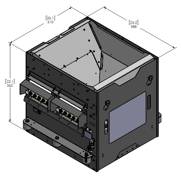
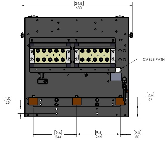
Single GrainGage Specifications and Dimensions
These images show the outer dimensions of the H2 and H3 Single GrainGage chassis.
 |
 |
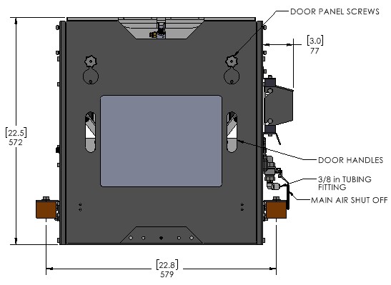 |
For more product specifications, refer to H2 Single GrainGage data sheet or H3 GrainGage data sheet.
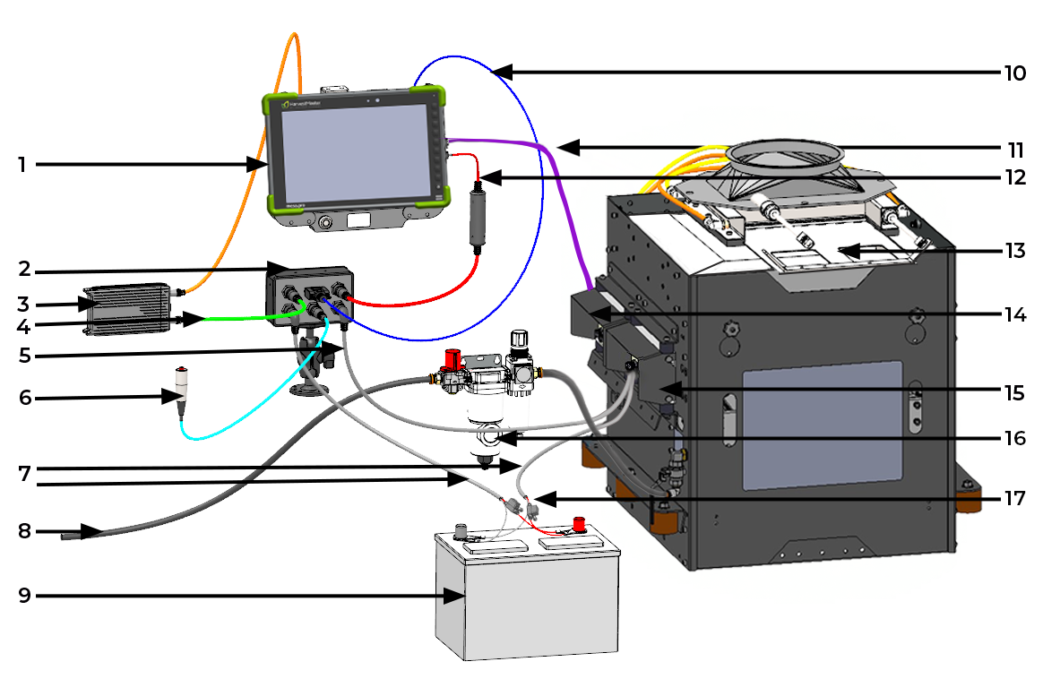
Single GrainGage System Diagram
|
|
|
|
|
|
|
|
|
|
|
|
|
|
|
|
|
* The orientation of the isolation gate may vary based on the combine.
Note: Use either the serial cable (10) or the CAN to USB cable (11). Do not use both at the same time.
Note: HarvestMaster requires that you install ATC 20 A fuses (16) on all power cables that connect to the battery.
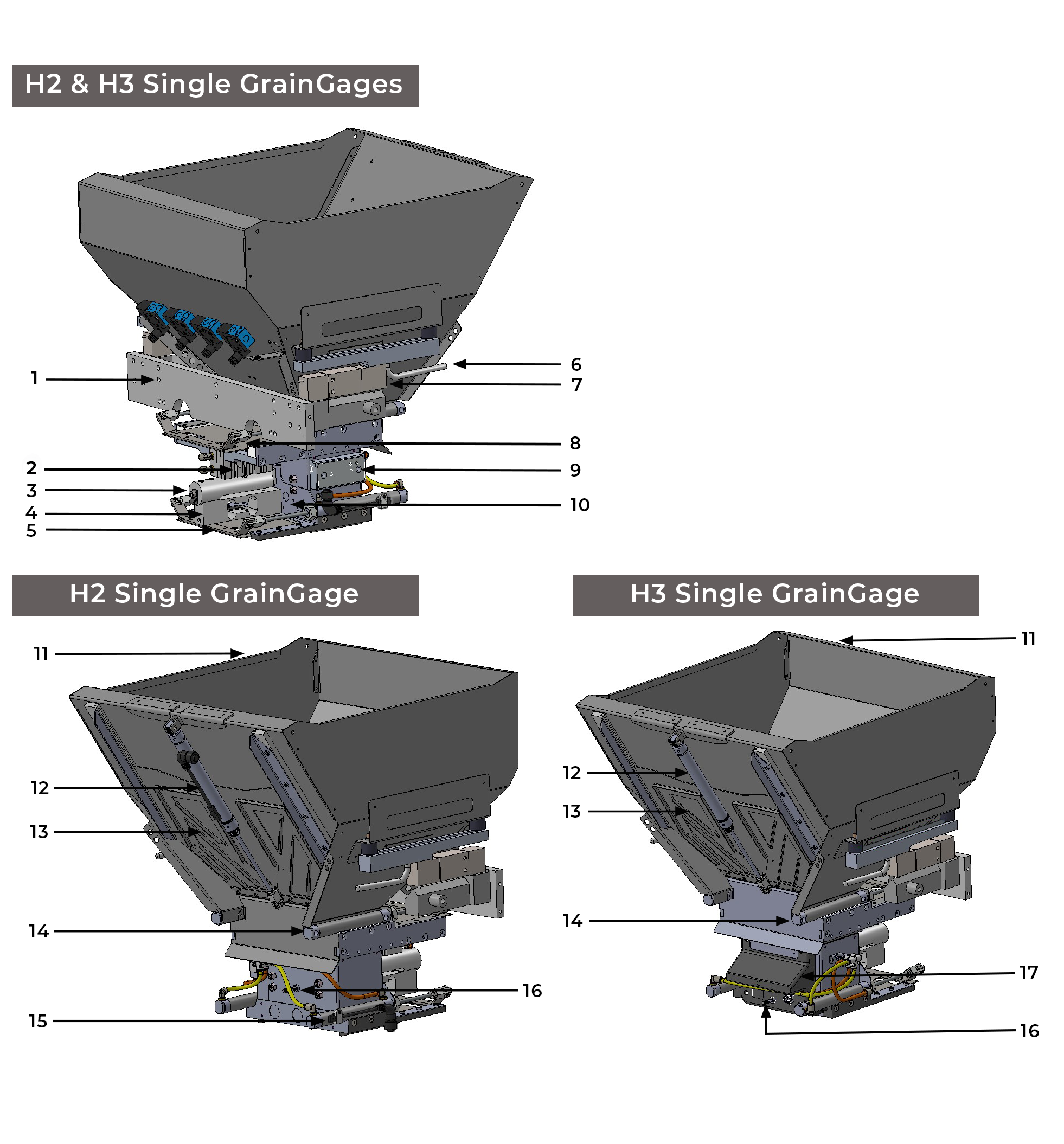
Internal Components of Single GrainGage
|
|
|
|
|
|
|
|
|
|
|
|
|
|
|
|
|
Single GrainGage System Components
| System Components | |
| Component | Description |
| DSP module |
The DSP is the electronics module that does the signal conditioning, measurement, and some control of the GrainGage. |
| Primary actuator module | The primary actuator module controls the top, bottom, separator, and evacuation gates. |
| H3 SCiO NIR Sensor |
This sensor uses near-infrared (NIR) technology to measure and analyze the moisture, protein, and oil (where applicable) of the test chamber sample. |
| EM3 moisture sensor |
This sensor measures the dielectric of the test chamber sample and converts that value to a grain moisture percentage according to the following formula. Percent moisture = 100 ( Mw / ( Md + Mw ) ) Mw is the mass of the water in the grain. Md is the mass of the grain. |
| System controller |
This electronics enclosure provides communications and signal interface to the GrainGage. The controller provides a serial communications interface, a remote enter button connection, a computer power supply, CAN (Control Area Network) connectivity, a USB connection, and system power switch. |
| Tablet |
A rugged tablet-style computer running Windows 10 or later operating system and the HarvestMaster Mirus software for field data collection. |
| Plot bucket |
The plot bucket holds the harvested plot. |
| Test chamber |
The test chamber measures the grain moisture and test weight for a sub-cycle. |
| Isolation gate |
The isolation gate prevents grain from dribbling or flowing into the plot bucket during a measurement cycle. |
| Top gate |
The top gate regulates the amount of grain entering the test chamber. |
| Bottom gate |
This gate, located at the bottom of the test chamber, closes to hold grain in the test chamber and opens to allow grain to flow out of the GrainGage. |
| Evacuation gate | The evacuation gate opens between cycles or plots to help evacuate the sample quicker. |
| Separator cylinder |
This pneumatic actuator moves the test chamber upwards into the filling position or downwards to the weighing position. |
| Load cell |
The system has three aluminum, full-bridge strain gauge load cells. Two are used to make precise weight measurements of the entire plot bucket of the GrainGage. The third load cell measures the weight of the test chamber contents. |
| Solenoid |
The GrainGage has five solenoids, which are controlled by the DSP and actuators module and independently open and close gates and separate/dock the test chamber. |
| Actuator (air cylinder) |
The gates in the GrainGage are actuated with pneumatic cylinders. |
| Limit switch |
The limit switch senses if the gates are closed. |
Terminology
| Terminology | |
| Term |
Definition |
| CAN |
The Control Area Network (CAN) is a robust electronic communication protocol common in automotive applications. |
| Weight trip cycle (strip mode) |
When the weight of the harvested grain in the plot bucket meets the trip weight threshold (trip point), the GrainGage processes each bucket of grain as a partial plot measurement. The data from each weight trip cycle are totaled (plot weight) or averaged (moisture, test weight, or NIR constituent data) for the entire plot. |
| Trip point (strip mode) |
The percentage of full bucket capacity at which a weight trip cycle will occur. |
| Trip weight threshold (strip mode) |
A weight provided by Mirus based off the set trip point. |
| Minimum weight threshold |
The minimum amount of weight required to include moisture, test weight, and NIR constituent data from that specific sub-cycle in the average for that plot. |
| Flush cycle |
The last cycle of the plot and Mirus advances to the next plot. |
| Sub-cycle |
A sub-cycle is a measurement of test weight, moisture, and NIR constituent data performed when the test chamber drops. The number of sub-cycles taken for each plot bucket of grain is adjustable in Mirus based off individual needs. Data for each sub-cycle is available in the backup file. |
| Plot weight |
The plot weight is the total weight of grain for an individual plot. This would be cumulative weight for all GrainGage weight-trip cycles within a plot. |
| Test weight |
The test weight is weight per unit volume of a sample of grain in the test chamber. Test weight is measured in lb/bushel or kg/hL. |
Inspect the GrainGage Shipping Crate
The GrainGage ships in a corrugated cardboard shipping crate and are secured with packing material. Upon delivery, inspect the shipping crate for any signs of damage. If you identify any damage, contact the shipping company to file a claim. The insuring agency must inspect the package before it is opened. If you do not find any issues with the shipping crate, open it and inspect the items you received.
![]() CAUTION: Do not open the shipping crate if you identify damage. Contact the shipping carrier of the insuring agency so that they can inspect the package before it is opened. Otherwise your claim may be denied.
CAUTION: Do not open the shipping crate if you identify damage. Contact the shipping carrier of the insuring agency so that they can inspect the package before it is opened. Otherwise your claim may be denied.
![]() CAUTION: Take care when unpacking the GrainGage. Use extra care with the weigh system load cells. Dropping one may result in permanent damage, which is not covered under HarvestMaster's standard warranty.
CAUTION: Take care when unpacking the GrainGage. Use extra care with the weigh system load cells. Dropping one may result in permanent damage, which is not covered under HarvestMaster's standard warranty.