Install the GrainGage
Classic GrainGage Components and Parts
The following tables list the standard components, installation parts, and optional accessories for the Classic GrainGage.
Standard Components and Accessories
|
Standard Components and Accessories |
||||
| PN | Qty | Description | Notes/Purpose | Photo |
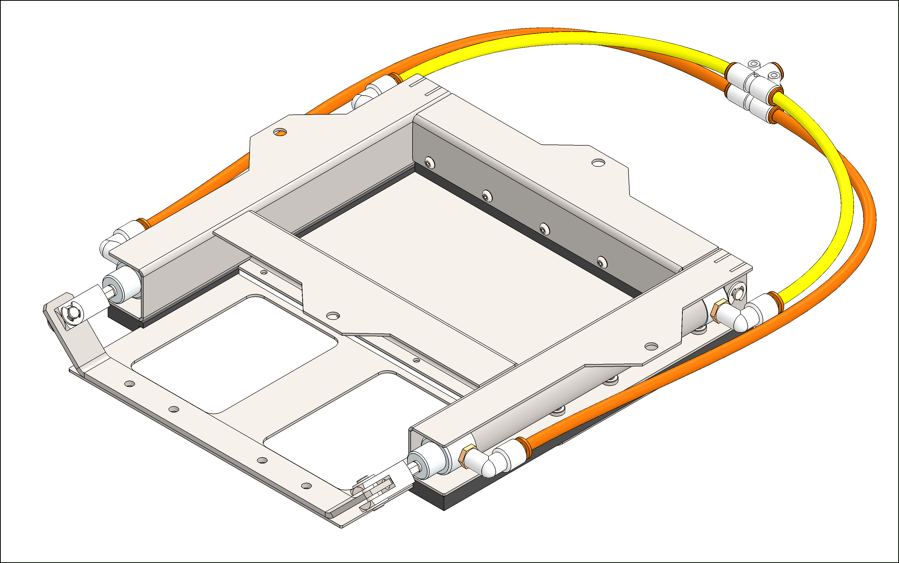
| 24404 | 1 | H2 Classic GrainGage (includes 10 hex-cap bolts for use in mounting) |
|
|
| 31004 | 1 | H3 Classic GrainGage (includes 10 hex-cap bolts for use in top mounting) |
|
|
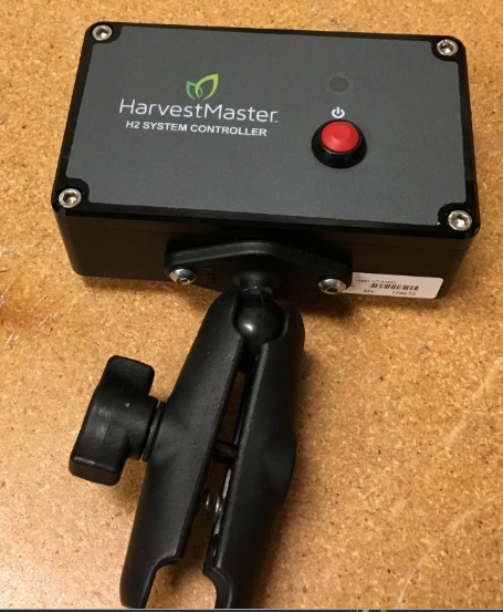
| 25030 | 1 | System controller with RAM mount and two button-head cap screws | Allows the operator to turn on/off the power to the GrainGage. |
|
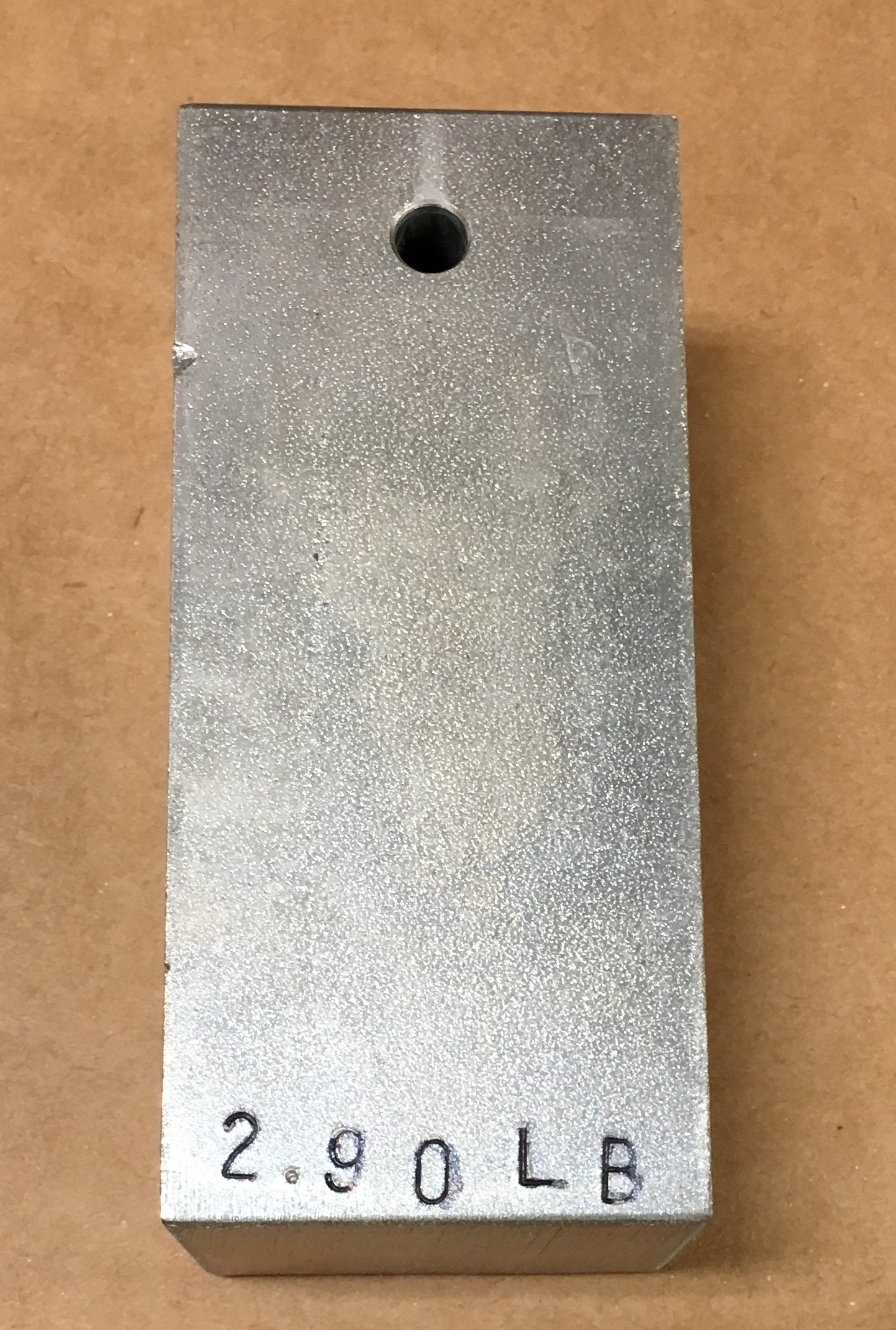
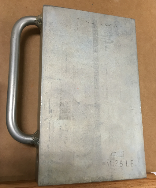
| 24407 | 1 | Test chamber calibration weight (approx. 3 lb (1.4 kg)) | Use the calibration weight (stamped with its precise weight) to calibrate the weight measurement of the test chamber. |
|
| 24408 | 1 | Plot bucket calibration weight (approx. 11 lb (5 kg)) | Use the calibration weight (stamped with its precise weight) to calibrate the weight measurement of the plot weight hopper. |
|
Classic GrainGage Installation Kit
| Parts Included in the Classic Installation Kit (PN26550) | ||||
| PN | Qty | Description | Notes/Purpose | Photo |
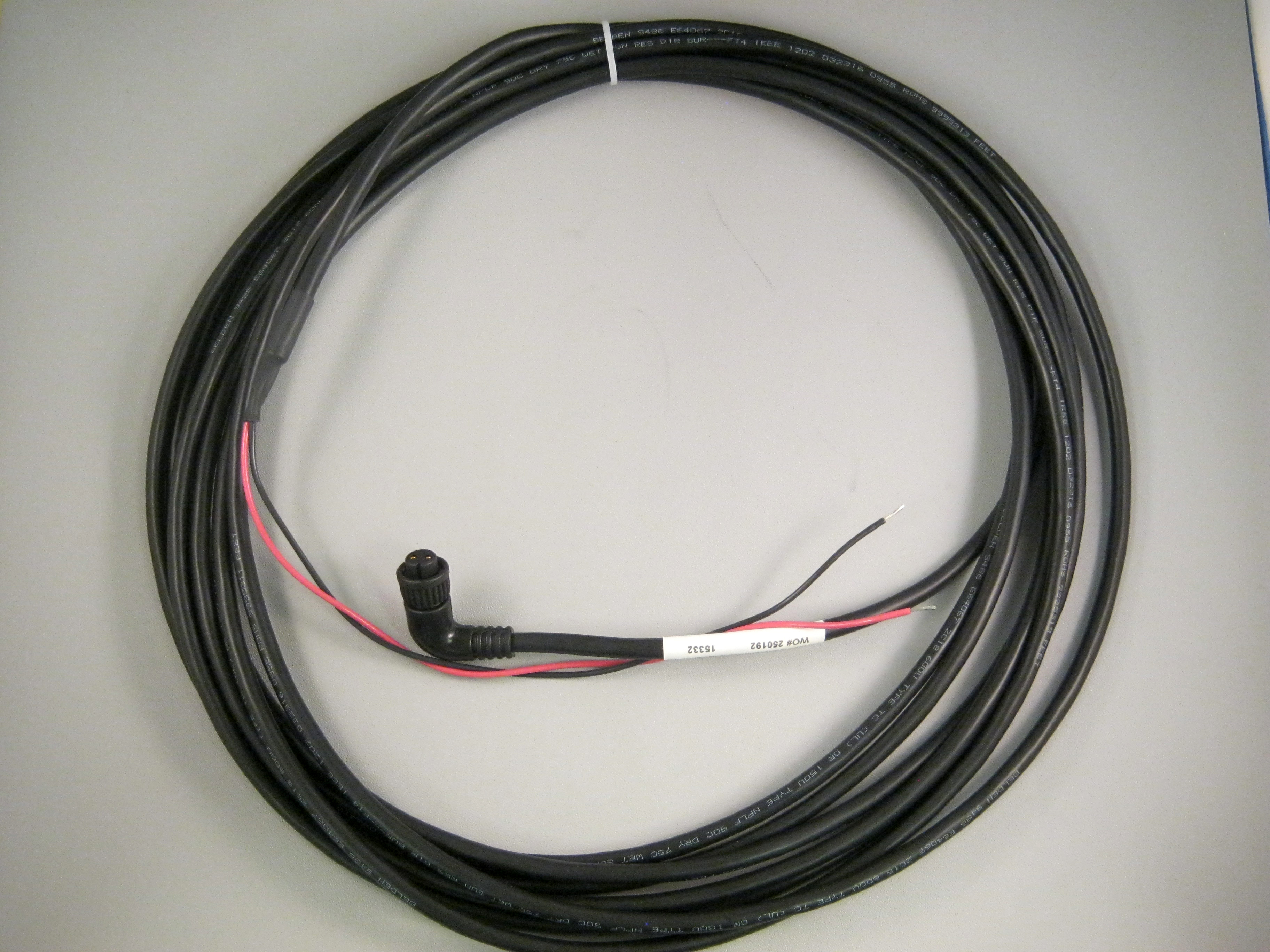
| 15332 | 2 | HM8 12 V DC power cable, 20 ft | One cable provides power to the system controller. The other cable provides power to the DSP module for signal conditioning . |
|
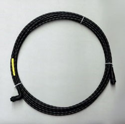
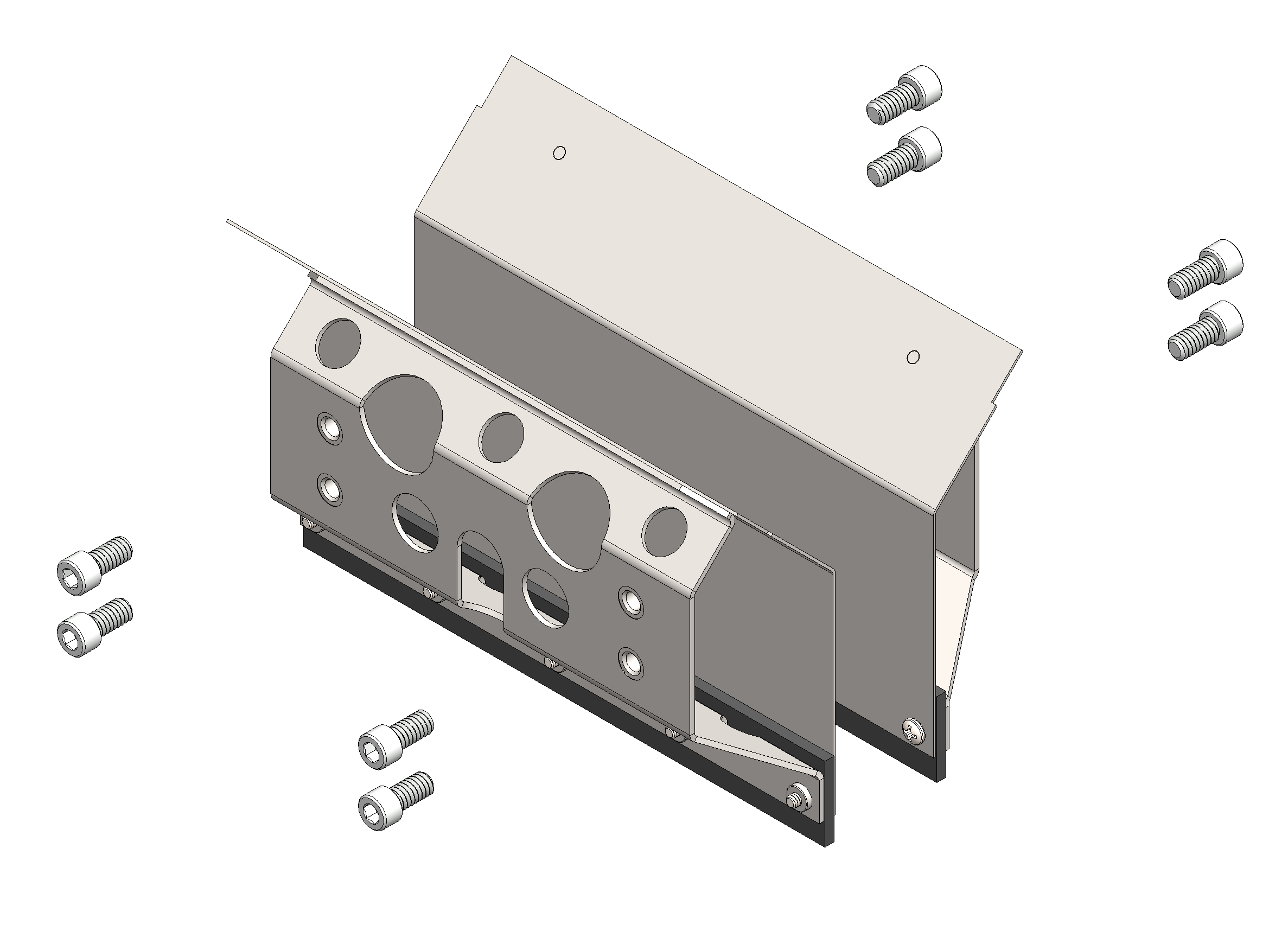
| 15336 | 1 | HM8 CAN communications cable, 25 ft | The CAN communications cable connects the system controller to DSP module on the GrainGage chassis. The end of the cable with the right angle connector connects to the DSP module. |
|
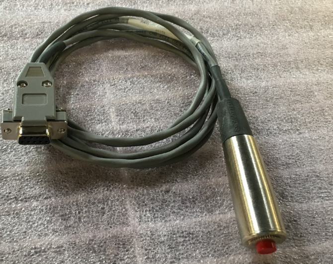
| 15374 | 1 | HM8 remote enter button and cable assembly | The remote enter button allows the operator to manually trigger a measurement cycle on the GrainGage. |
|
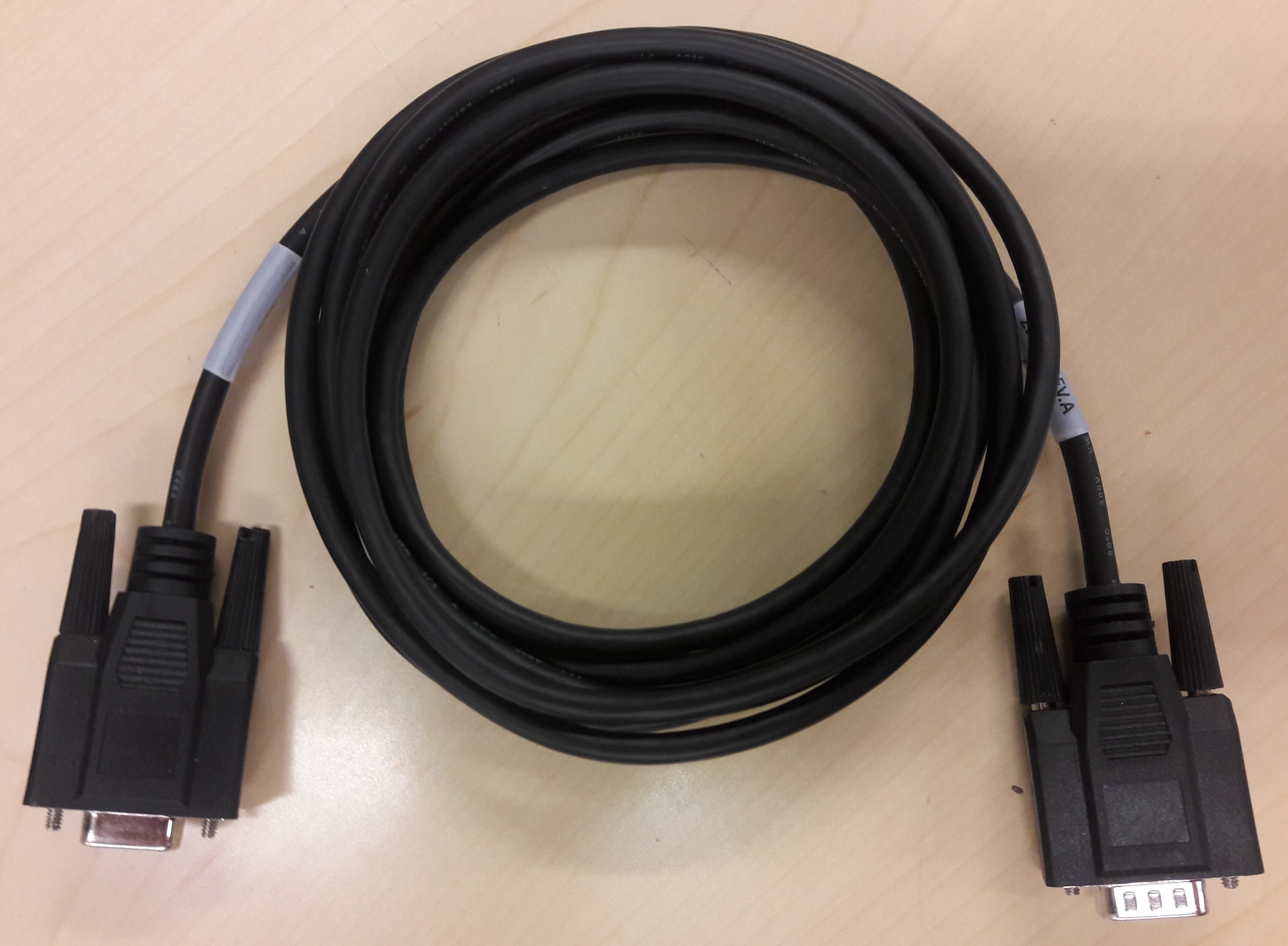
| 23237 | 1 | HM 9-pin serial cable, 10 ft (3 m) |
The serial cable connects the computer to the system controller. |
|
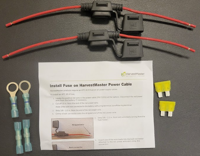
| 1 | HM fuse kit | The kit includes the materials and instructions for installing fuses on the battery cables connected to the GrainGage. |
|
|
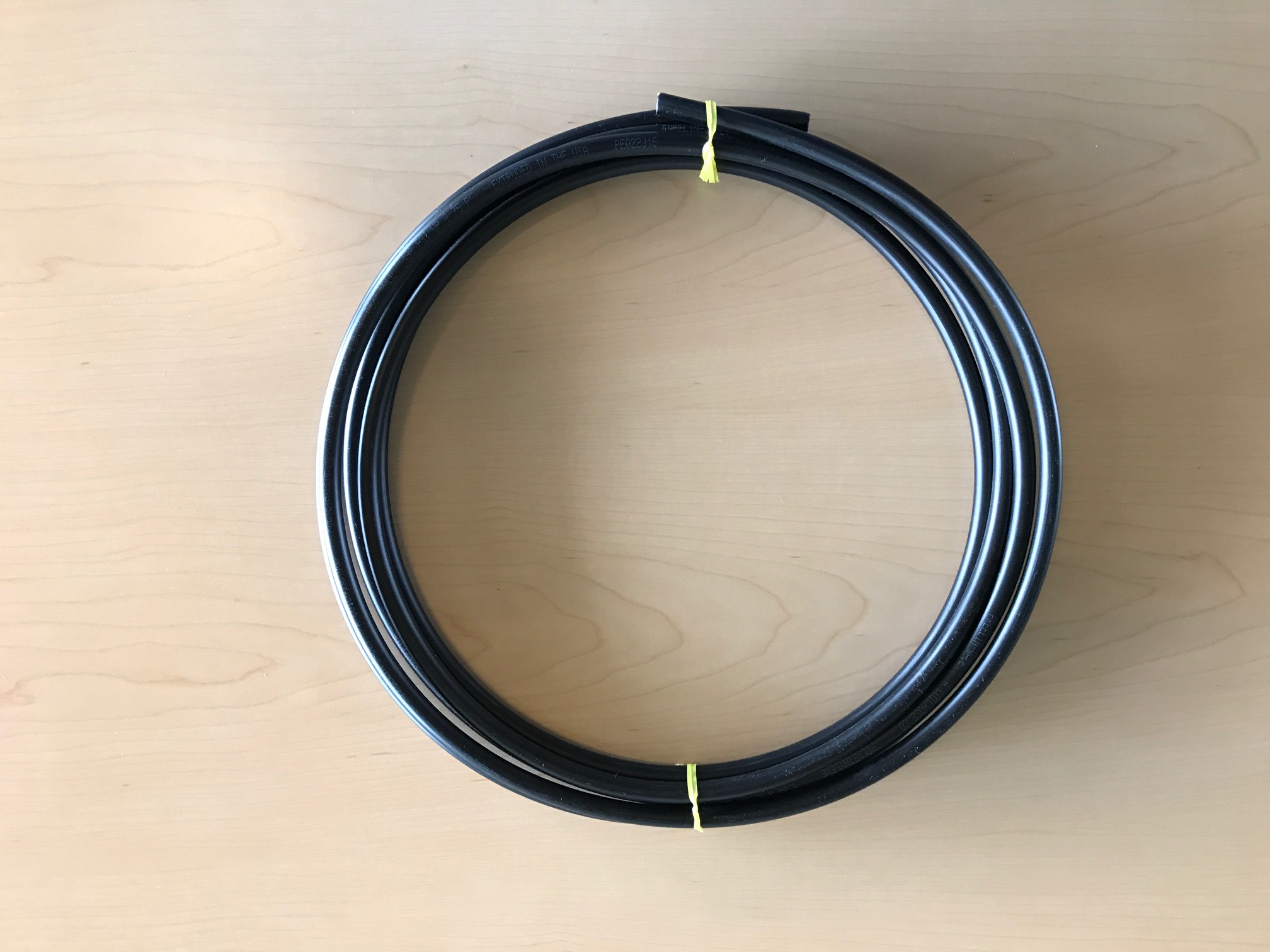
| 9455 | 30 ft | PLS polyurethane tubing 0.375 in. OD, 0.250 in. ID | This tubing provides pressurized air to the GrainGage. |
|
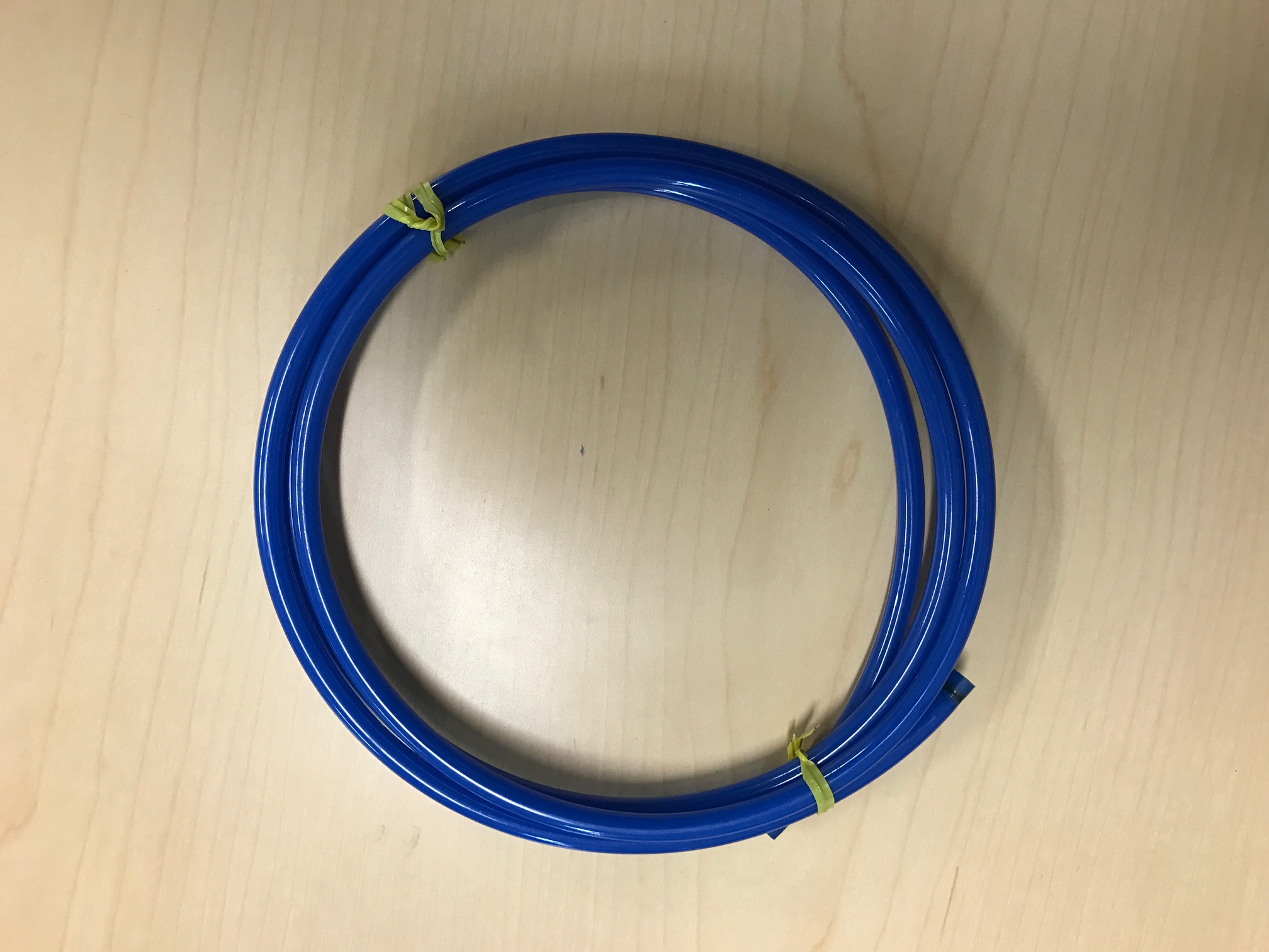
| 9592 | 5 ft | PLS polyurethane tubing 0.25 in. OD, 0.16 in. ID | This tubing connects the auxiliary pneumatic actuator to its pneumatic control valve. |
|
Optional Parts
Use these parts as needed for your unique installation.
| Accessories | ||||
| PN | Qty | Description | Notes/Purpose | Photo |
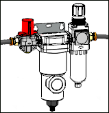
| 15450 | 1 | Pneumatic air prep (regulator) | Use between the air tank and the GrainGage to regulate or shut off air pressure and to remove oil aerosols, liquids, and fine particles. |
|
| 26530 | 1 | Isolation gate kit | Add an isolation gate if your combine doesn’t already have one. |
|
| 26545 | 1 | H2 low yield insert kit | (H2 only) Use the low yield insert kit to measure test weight and moisture in low volume plot samples that don’t fill the test chamber. |
|
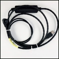
| 26566 | 1 | DSP I/O actuator cable | Connects to GPIO 1 of the DSP module and breaks out the actuator 5 & 6 controls. |
|
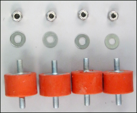
| 26622 | 1 | Classic rubber isolation kit | The kit includes
|
|
| 27092 | 1 | HMS USB-CAN right angle connector | Use for troubleshooting. |
|
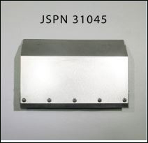
| 31045 | 1 | H3 low yield insert subasy kit | (H3 only) Use the low yield insert kit to measure test weight and moisture in low volume plot samples that don’t fill the test chamber. |
|
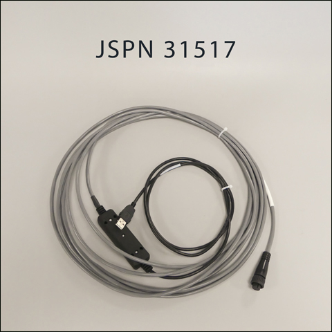
| 31517 | 1 | SCiO serial to USB cable | (H3 only) This cable connects the SCiO Sensor junction on the GrainGage to the tablet. |
|
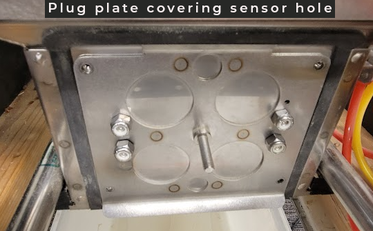
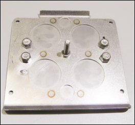
| 31740 | 1 | H3 sensor hole plug subasy kit | (H3 only) Covers the SCiO Sensor hole in the test chamber. Install if you are using an EM sensor. |
|
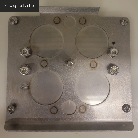
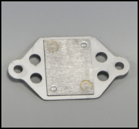
| 31796 | 1 | H3 moisture sensor plug plate subasy kit | (H3 only) Covers the EM sensor hole in the test chamber. Install if you are using a SCiO Sensor. |
|
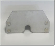
| 31798 | 1 | H3 low yield insert plug plate kit | (H3 only) Covers holes in the test chamber. Install if you are not using the low yield insert. |
|
Tablet Computer Options
Below are the rugged tablet computer options for running Mirus and operating the GrainGage.
| Tablet Computer Options | |||
| PN | Description | Notes/Purpose | Photo |
| ST1-112 | Mesa® Pro | 10-inch ultra-rugged tablet computer running Microsoft® Windows 11 |  |
| MS4-CFG | Mesa 4 | 7-inch ultra-rugged tablet computer running Windows 11 | .png) |
| MS3-CFG or MS3A-CFG | Mesa 3 | 7-inch ultra-rugged tablet computer running Windows 10 or Android 11 | |
| 25681 | Mesa powered vehicle dock | Powered vehicle dock for the 7-inch Mesa 3 or Mesa 4 tablet computer | 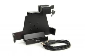 |
Installation Types
Install the GrainGage on a combine or use as a stand-alone deployment with a stationary threshing operations. On a combine, the GrainGage supports either top mounting or base mounting.
 |
 |
 |
|
Top Mounting |
Base Mounting |
Stationary Deployment |
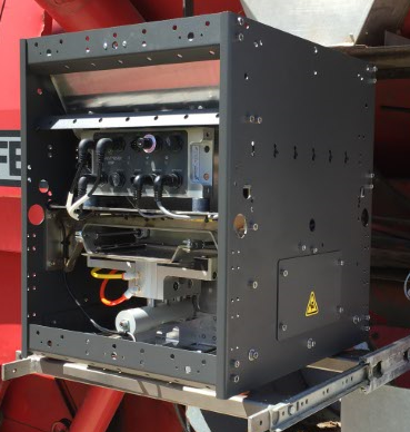
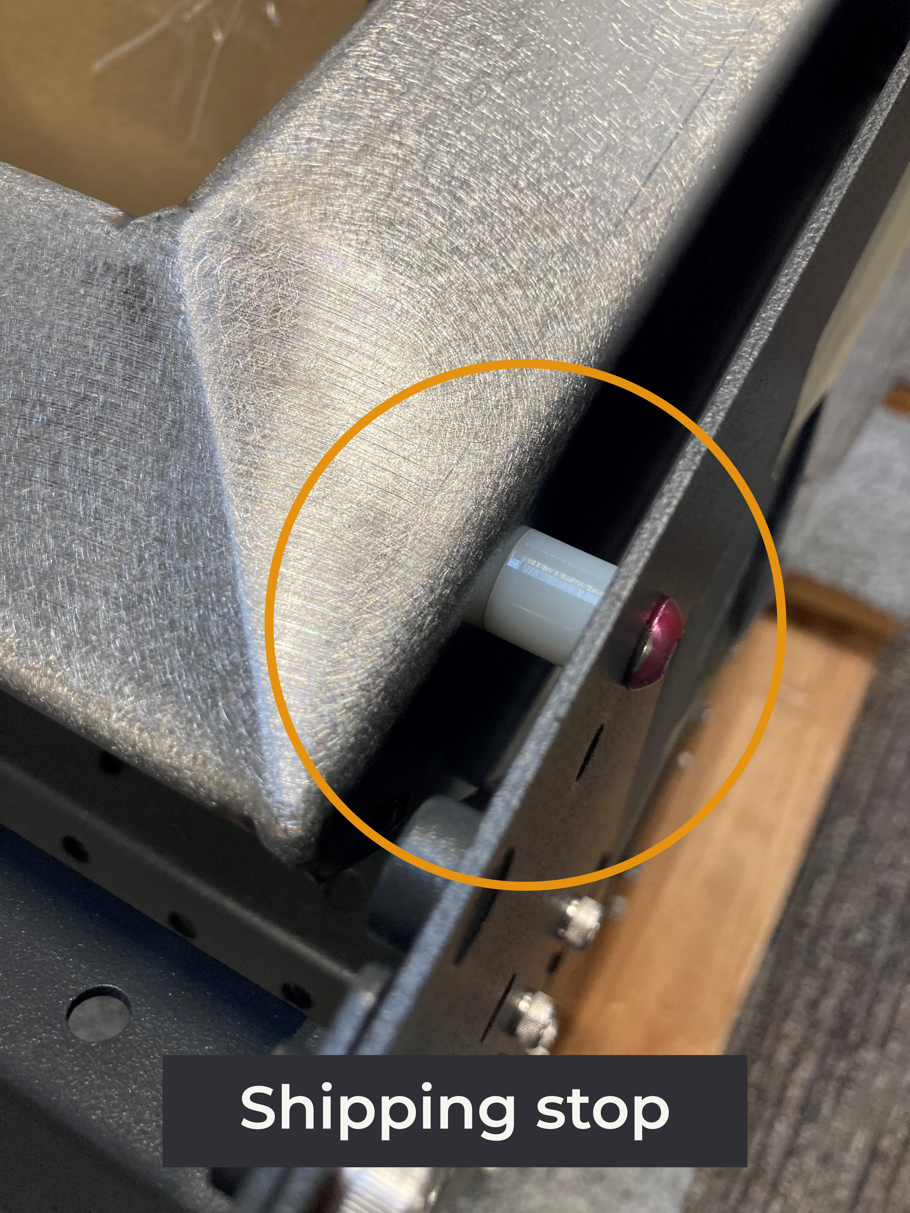
Remove Shipping Stops
During shipping, four shipping stops stabilize the weigh bucket and prevent damage to the GrainGage. Each shipping stop is held in place by a red bolt and nut.
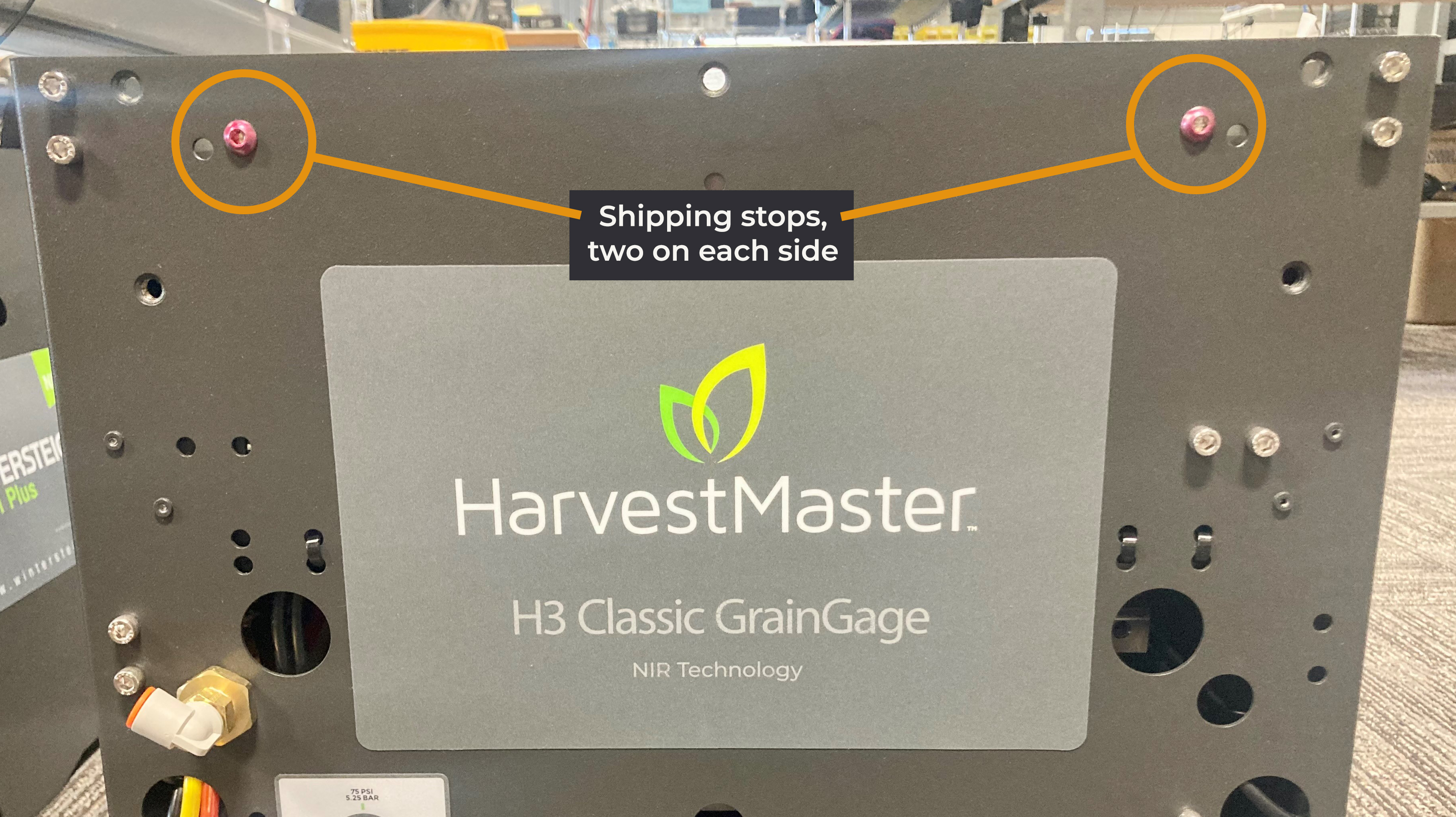
Before installing and using the GrainGage,
- Remove the shipping stops and the bolts and nuts holding the shipping stops in place.
Install on a Combine
To install the GrainGage on a combine,
- Park the combine on a level surface and check the tire pressure to make sure all tires are at normal operating pressure.
- Identify the location on the combine where the GrainGage will be mounted. When selecting a location, allow enough clearance to remove access panels and perform maintenance, daily checks, and repairs.
- Mount the GrainGage on the combine. Ensure it is straight and level. The GrainGage can be mounted on slides or a robust hinging mechanism to give better access for calibration and maintenance. Options for slides are available from http://www.generaldevices.com.
- Use the parts from the rubber mounting kit (PN 26622) to cushion the GrainGage from the mechanical shocks of the operating plot combine.
If the GrainGage is mounted in a location where you cannot see the grain flow and the gates moving, consider mounting a camera to allow observation of the gates and the grain as it flows through the system. Commercially available vehicle backup camera systems can serve this purpose.
Install the System Controller, Tablet, and Cabling
The system controller switches power to the system and indicates the status of operation. It also charges the tablet computer (12 V DC, maximum 12 A unregulated), provides the connection point for the remote enter switch, and serves as the CAN interface between the GrainGage and the tablet computer.
To install the system controller and tablet computer on the combine,
- Identify mounting locations in the cab for the system controller and the tablet computer. Position the tablet computer and controller within easy reach and view of the operator and close enough to allow serial cable (PN 23237) or CAN to USB cable (PN 27092) to reach between them.
 CAUTION: Prevent premature wear or damage to the connectors by providing strain relief for the connections so that the weight of the cable does not pull on the connectors.
- Use the RAM mount in the appropriate position for your installation.
- Mount the tablet computer in the desired location.
- Determine the route of cables and hoses that keeps them out of the way of moving parts. If routing cables along existing cables or hoses, use plastic zip ties to hold them in place (at least one tie every 2 ft (.6 m)).
CAUTION: Ensure the cables are free from pinching or kinking during use and maintenance to prevent damage to the cables.
- Route the power cables (PN 15332). Route one power cable between the system controller and the battery, and route the other power cable between the DSP moduleDSP module and the battery. Trim each power cable to length on the pig tail end to suit the installation. The pig tail end of each cable is for connection to the battery.
- Install an ATC 20 A fuse (included) on all power cables leading to the battery to protect the GrainGage and system controller and reduce the risk of fire if your cable is damaged. (For installation instructions, see Install Fuse on HarvestMaster Power Cables.)
- Route the CAN cable (PN 15336) from the system controller to the DSP module on the GrainGage.
- For the H3 Classic GrainGage, route the SCiO serial to USB cable (PN 31517) from the SCiO Sensor junction cable (PN 30712) on the outside of the GrainGage to the rugged tablet.
![]() CAUTION: The GrainGage requires a clean 12 V DC supply in the range of 11.5 V to 18.0 V. The power supply must be free of transient power spikes.
CAUTION: The GrainGage requires a clean 12 V DC supply in the range of 11.5 V to 18.0 V. The power supply must be free of transient power spikes.
![]() CAUTION: When using a battery booster for welding on the machine or to furnish a quick charge on the combine battery, disconnect the GrainGage power source to prevent damage. DC voltages over 18 V will damage GrainGage electronics. Many automotive battery boosters exceed 18 V.
CAUTION: When using a battery booster for welding on the machine or to furnish a quick charge on the combine battery, disconnect the GrainGage power source to prevent damage. DC voltages over 18 V will damage GrainGage electronics. Many automotive battery boosters exceed 18 V.
Install a Pressurized Air Supply
The GrainGage requires pressurized air between 75‒85 PSI. The air tank must be at least two gallons and must have a water drain petcock valve on the bottom. Use a pneumatic conditioner and air shutoff (PN 15450 or similar) between the air tank and the GrainGage to regulate the pressure and to remove oil aerosols, liquids, and fine particles. The air supply should have a filtration of 5 micron or smaller. HarvestMaster recommends using the air filter from your combine engine.
Note: Before mounting anything, make sure the air hose can reach from the air tank to the pneumatic condition and shutoff, and the ⅜ in. poly tubing can reach the GrainGage.
To install a pressurized air supply,
- Mount the air tank in a location that allows the operator to drain the tank daily.
- Mount the pneumatic conditioner and shutoff. Ensure the operator can access the shutoff valve.
- Connect the air hose from the air tank to the pneumatic conditioner and shutoff.
- Connect air from the pneumatic conditioner and shutoff to the GrainGage with ⅜ in. poly tubing.
![]() CAUTION: Lubricating the actuators and solenoid valves in the GrainGage system may lead to premature failure of these components.
CAUTION: Lubricating the actuators and solenoid valves in the GrainGage system may lead to premature failure of these components.
Add the Isolation Gate Kit
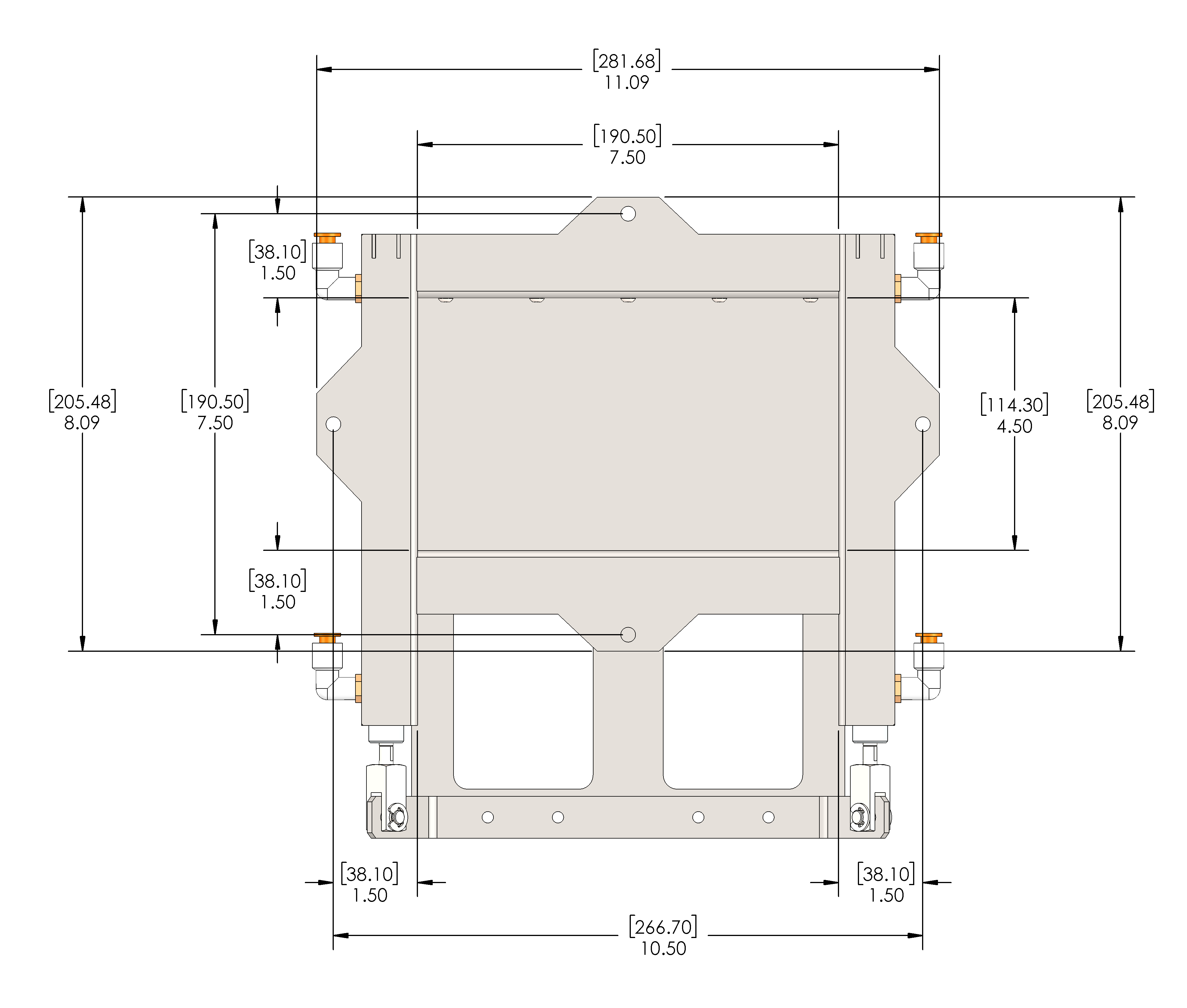
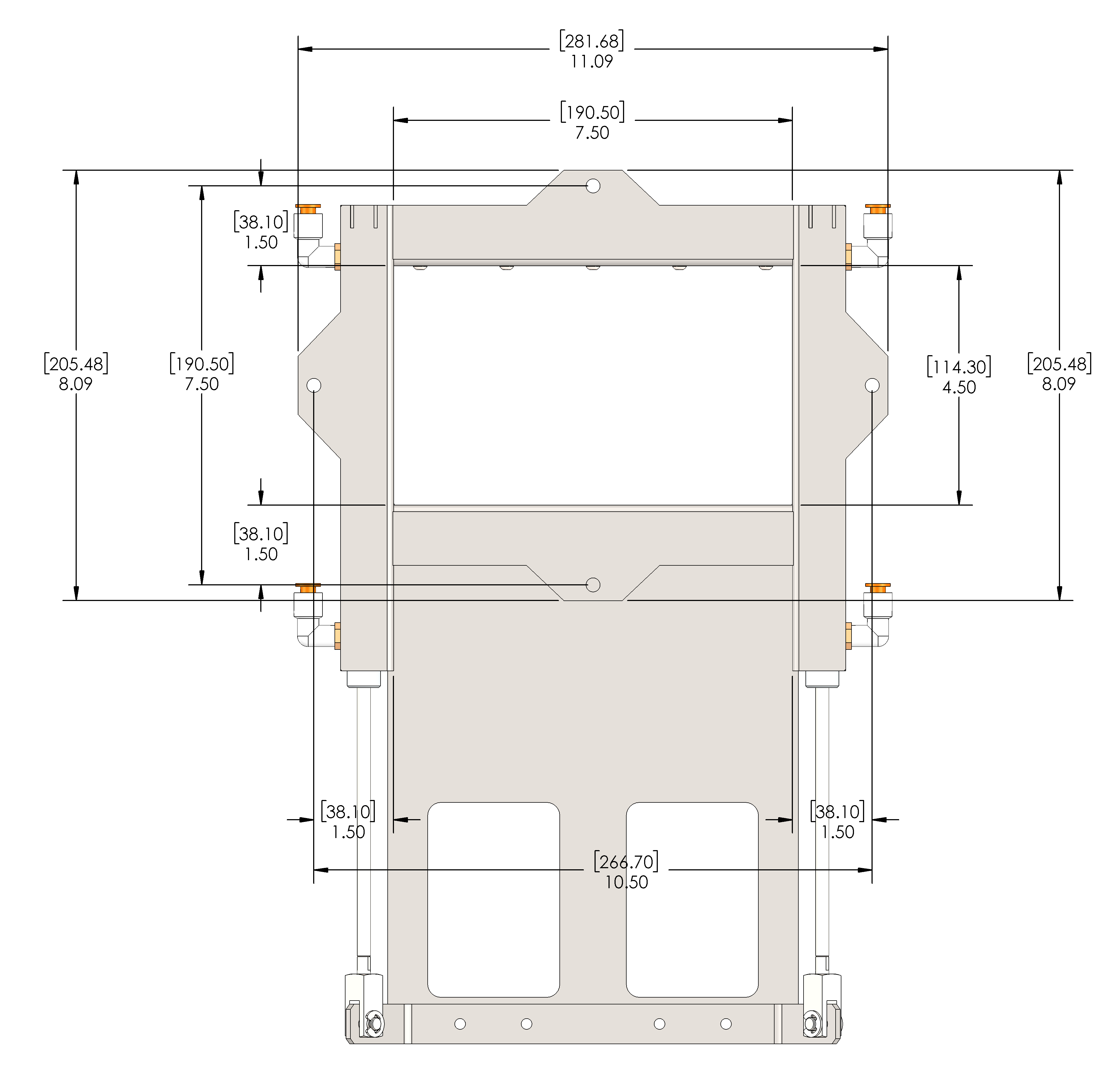
The Isolation Gate Kit is optional but recommended if your combine does not already have an isolation gate. The isolation gate halts grain flow into the GrainGage during a measurement cycle. When installing, ensure the cyclone has sufficient holding capacity above the isolation gate to accommodate the grain flow for several seconds while the measurement sequence executes.
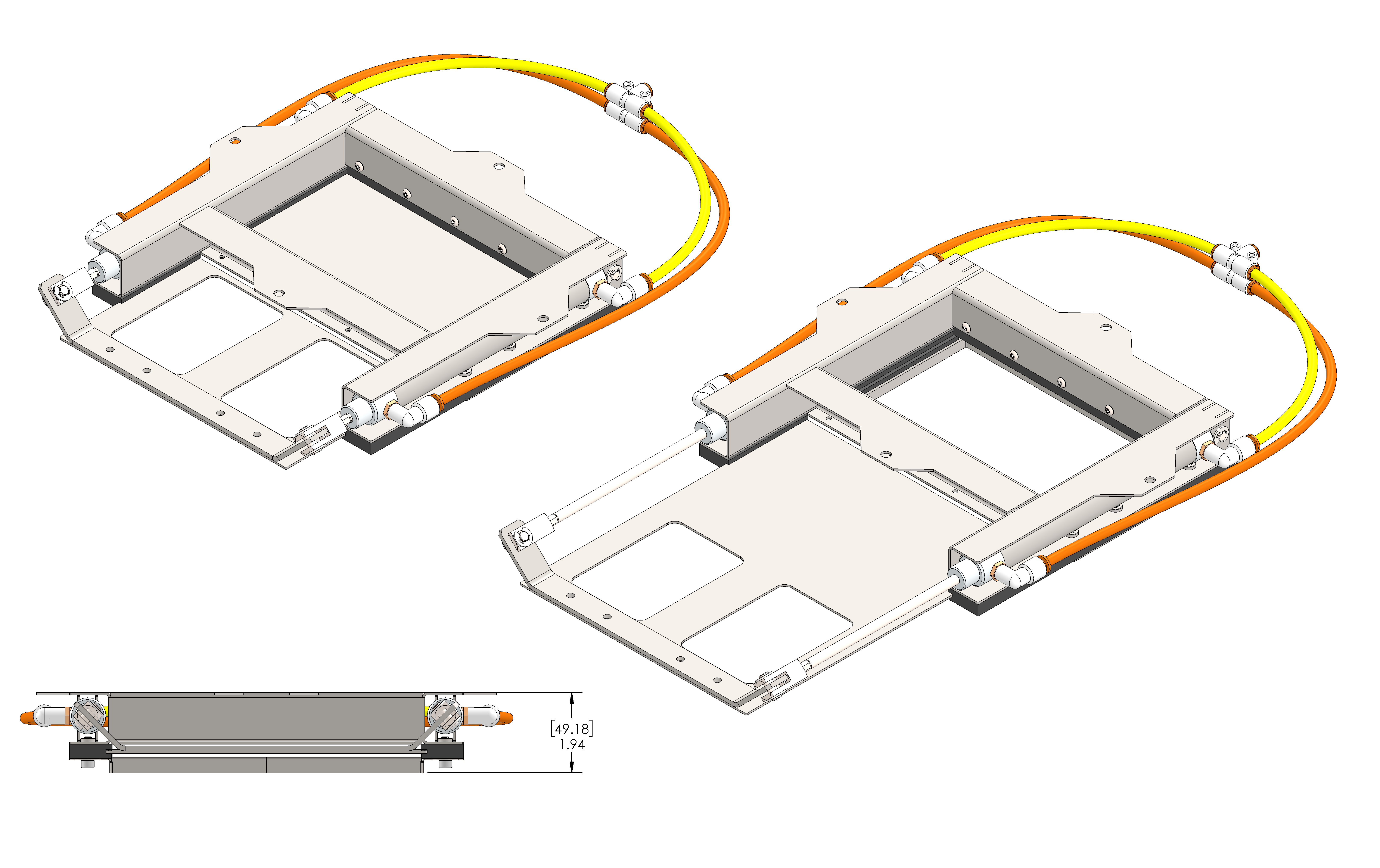
The following drawings show the dimensions of the isolation gate in the closed and open positions. The drawings appear in inches and millimeters.
Add Low Yield Inserts to the Test Chamber
Low yield inserts make it possible for the GrainGage to measure test weight and moisture for smaller plot samples. The number of inserts you can install and the process you use for installing the inserts depends on whether you are using an EM sensor or a SCiO sensor in your GrainGage. See Appendix A: Volume, Weight, and Industry Standard Values for volume and weight requirements.
| Low Yield Inserts | |||
| GrainGage Model | Sensor Type | Part Number | Installable Inserts |
| H2 Classic GrainGage | EM Sensor | 26545 | One or Two |
| H3 Classic GrainGage | SCiO Sensor | 31045 | One |
| EM Sensor | 31045 | One or Two | |
Note: The low yield inserts are designed specifically for each GrainGage model and are not interchangeable.
Add Low Yield Inserts with the EM Sensor
With the EM sensor, you can install one or two low yield inserts. The holes in the test chamber for the low yield inserts are plugged by two metal plates (one on each side) with four hex nuts.
To install a low yield insert,
- Open the bottom gate.
- Remove the low yield plug plate from the side on which you want to install the low yield insert. Save the plates and nuts to cover the holes when the inserts are removed.
Note: If you are using only one insert, install the insert on the side where the calibration weight hangs.
- Slide the insert up and into the test chamber. Begin the insertion between the pressed in nuts on the bottom of the test chamber.
- Angle and rotate the insert as you slide it into place against the wall of the test chamber.
- Secure the insert with four hex-drive, socket-cap screws (¼-20 x 0.5 in.).
- Repeat this procedure to install a second insert on the other side of the chamber.
Add a Low Yield Insert with the SCiO Sensor (H3 Only)
With the SCiO Sensor, you can install one low yield insert in the test chamber on the side opposite the SCiO Sensor. The holes in the test chamber for the low yield insert are plugged by a metal plate with four hex nuts.
To install the low yield insert,
- Open the bottom gate.
- Remove the low yield plug plate from the wall of the test chamber opposite the SCiO sensor.
- Slide the insert up and into the test chamber. Begin the insertion between the pressed in nuts on the bottom of the test chamber.
- Angle and rotate the insert as you slide it against the wall opposite the SCiO Sensor.
- Secure the insert with four hex-drive, socket-cap screws (¼-20 x 0.5 in.).
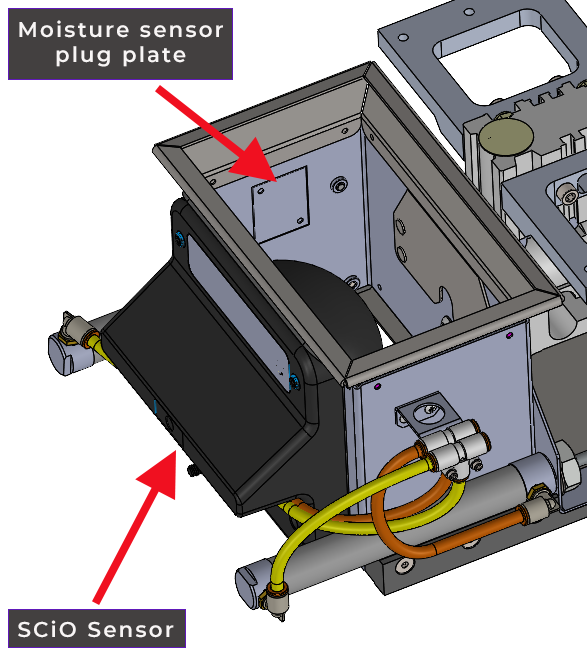
Change the Moisture Sensor (H3 only)
The H3 Classic GrainGage uses either a SCiO Sensor or an EM sensor for detecting moisture. The SCiO Sensor comes with the H3 Classic GrainGage, and the EM sensor can be purchased separately. Use the instructions below to change the moisture sensor installed in the H3 Classic GrainGage.
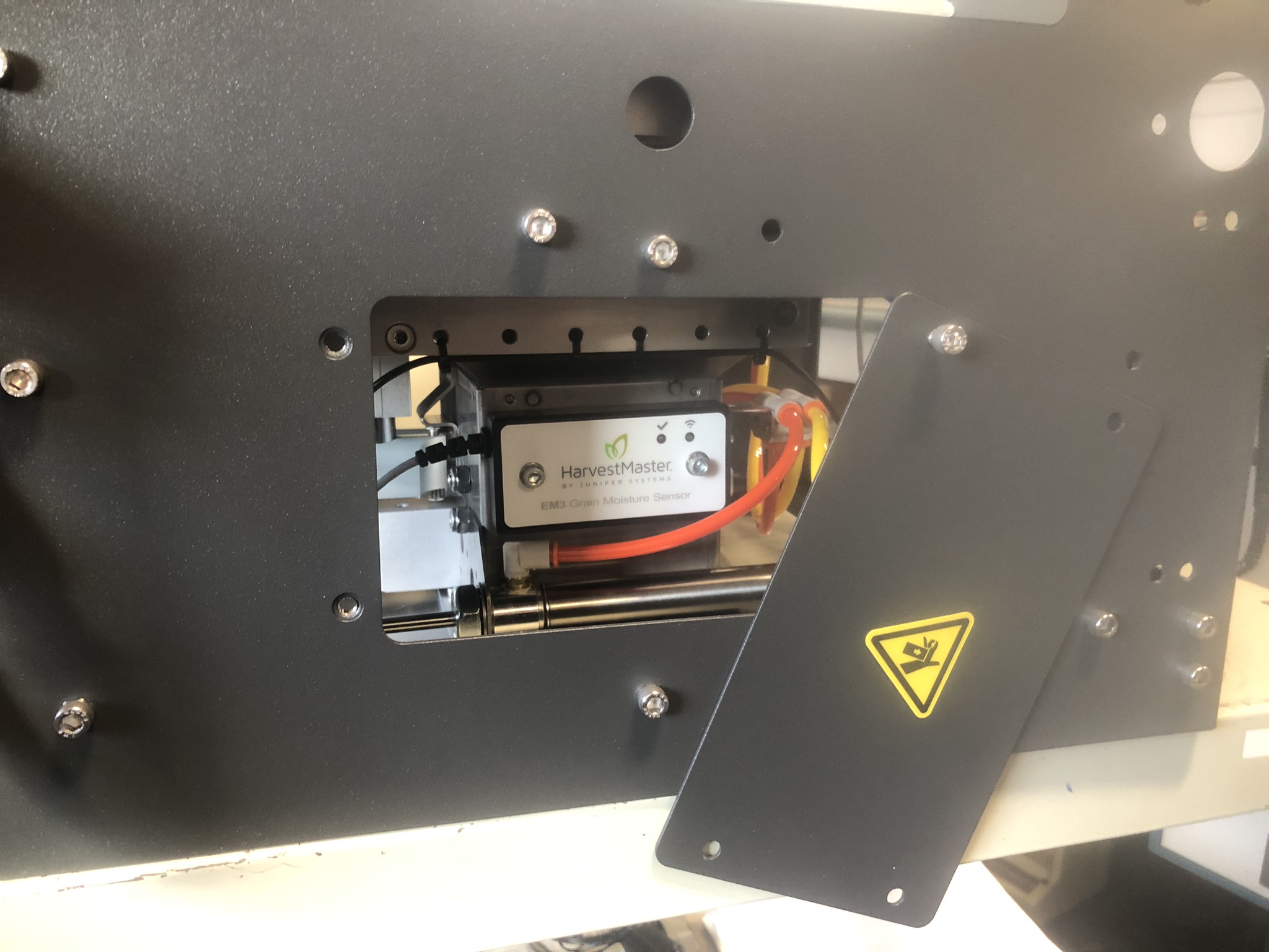
Install EM Moisture Sensor
To install the EM sensor in the H3 Classic GrainGage,
- Remove the side access panel.
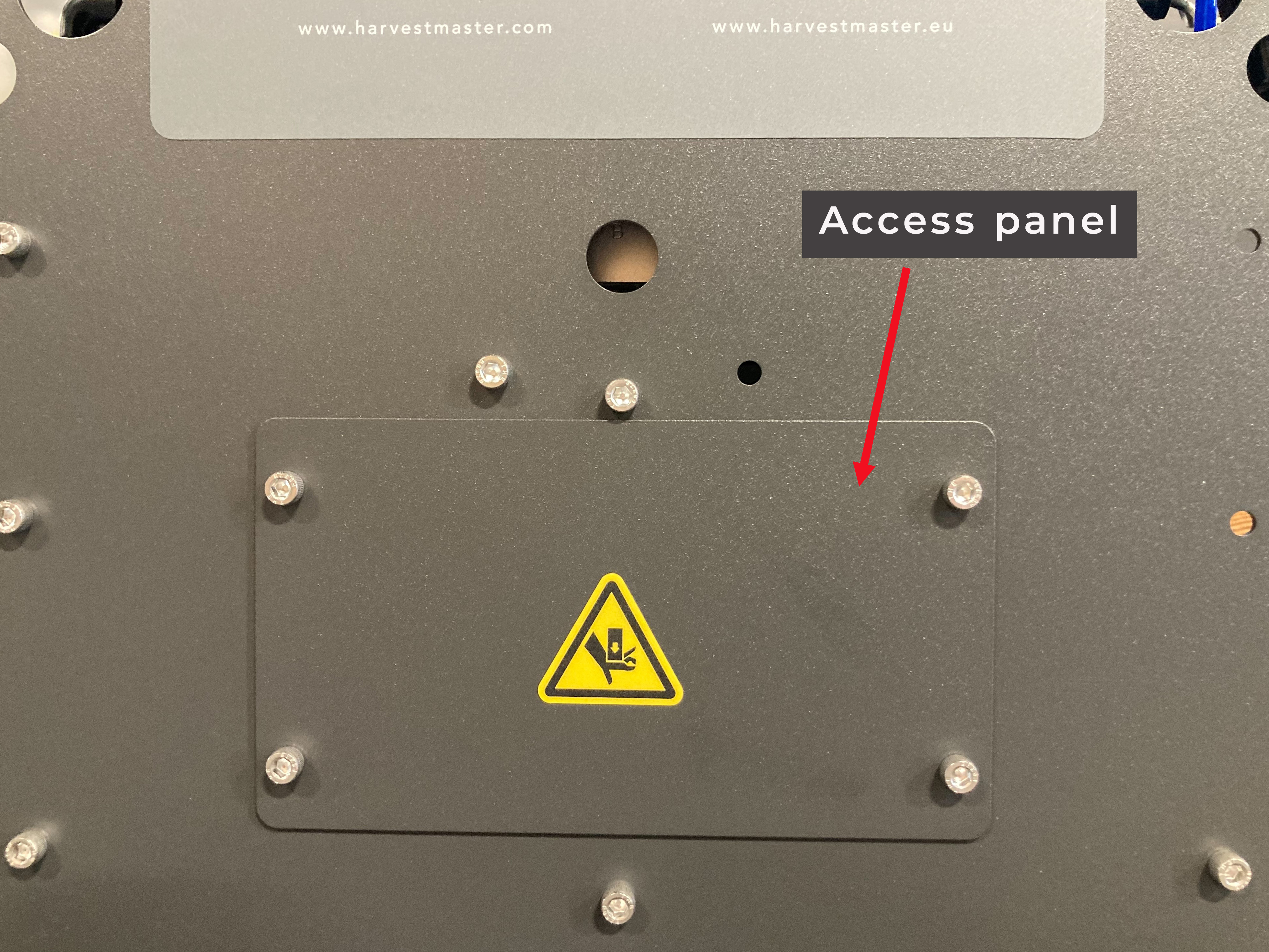
- Remove the EM moisture sensor plug plate from the exterior of the test chamber. Save the plug plate and screws for future installation.
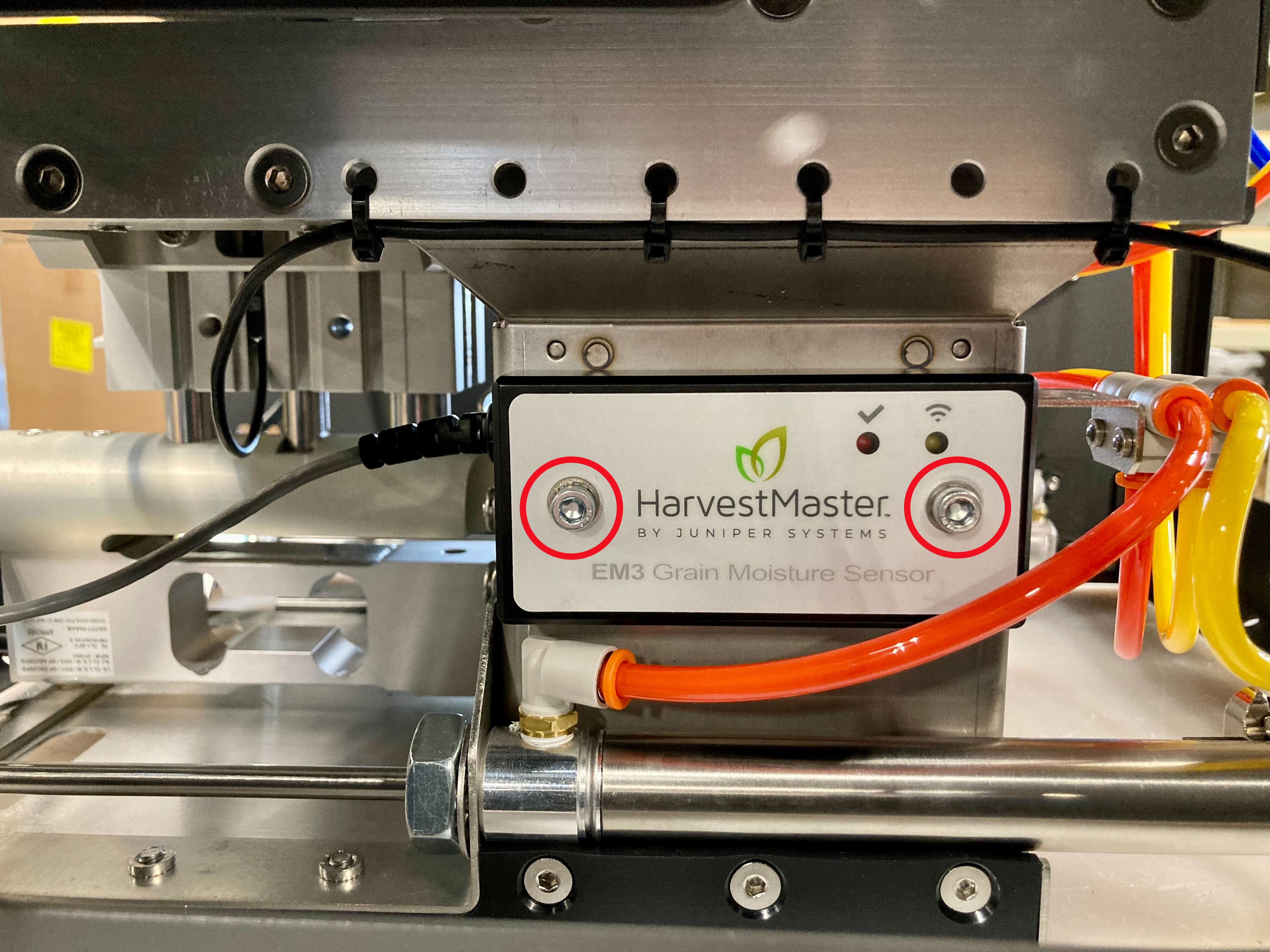
- Insert the EM sensor into the opening on the test chamber. Ensure the label on the EM sensor is facing up.
- Secure the EM sensor to the test chamber with two captive screws.
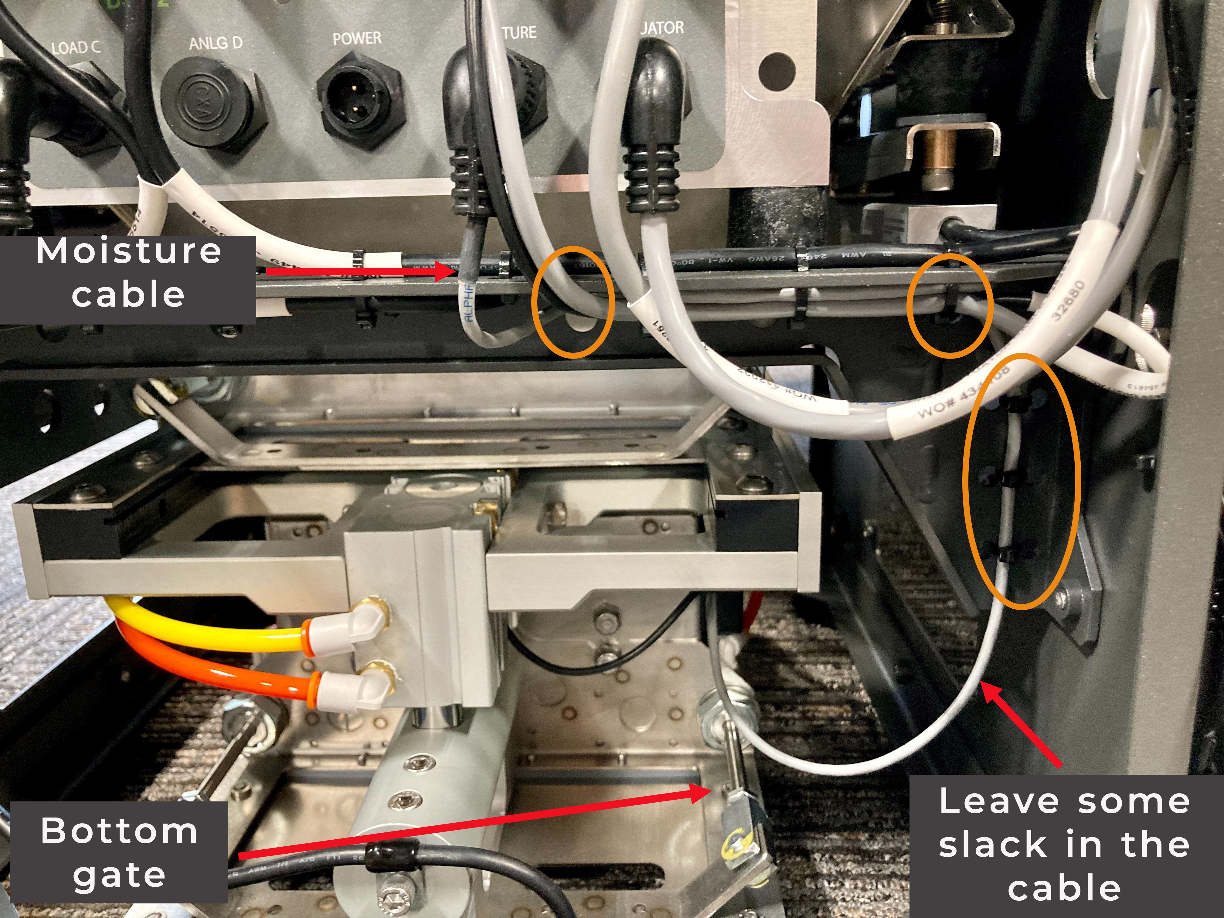
- Route the EM sensor moisture cable along the GrainGage frame to the DSP module.
- Attach the moisture cable to the DSP moisture port.
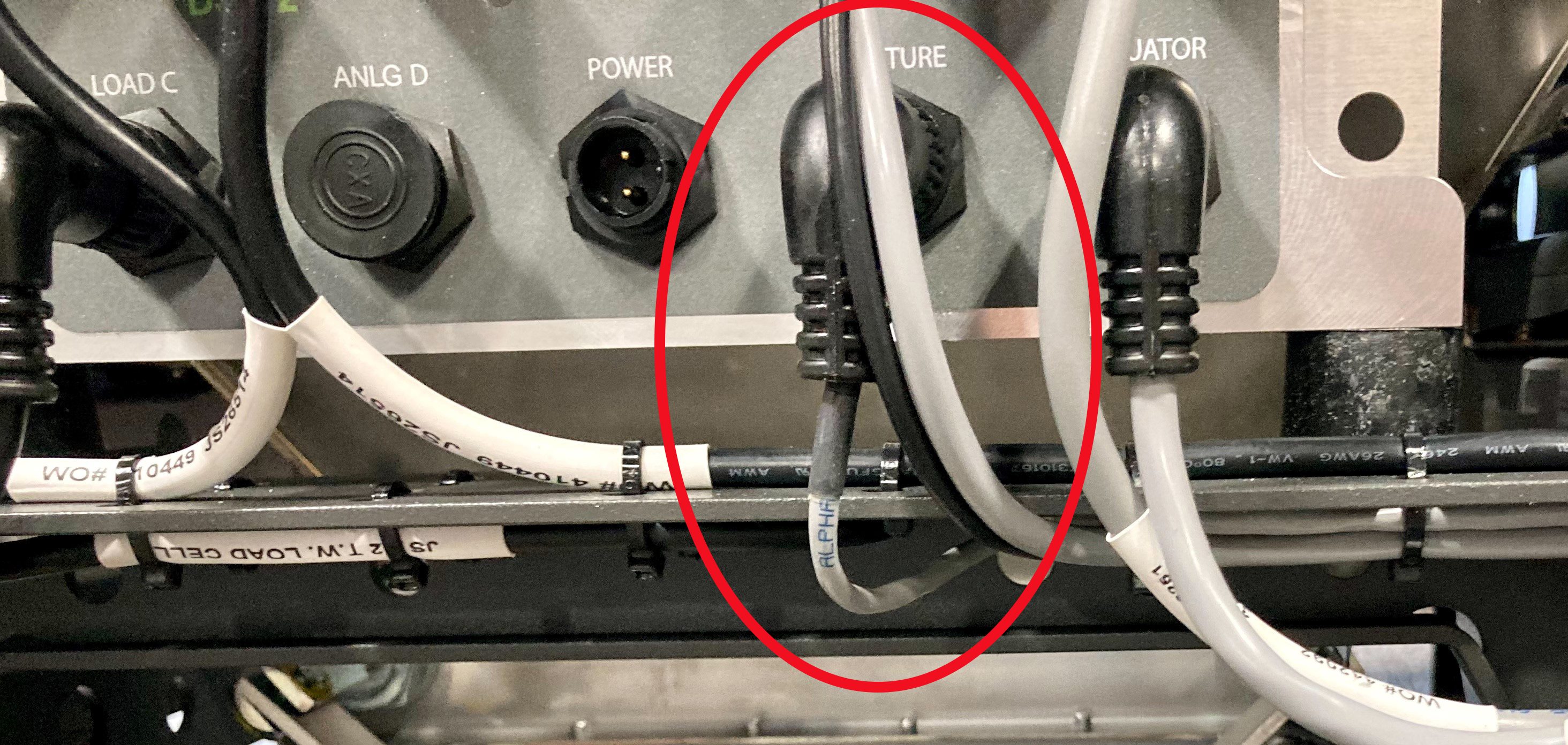
- Use zip ties to secure the moisture cable to the GrainGage frame, as shown.
For best results,- Leave enough slack in the moisture cable so that it does not pull on the test chamber and interfere with the weight measurement.
- Ensure the moisture cable does not touch the bottom gate.
- Reinstall the side access panel on the GrainGage.
Remove the EM Sensor
To remove the EM sensor,
- Remove the side access panel on the GrainGage.
- Remove the two captive screws that secure the EM sensor.
- Slide out the EM sensor.
- Cut the zip ties securing the moisture cable to the GrainGage frame.
- Disconnect the EM moisture cable from the DSP moisture port.
- Cover the opening for the EM moisture sensor with the H3 moisture sensor plug plate (PN 31796). Attach it to the test chamber with two 8-32 x 3/16 SS button head socket head cap screws.
- Reinstall the side access panel on the GrainGage.
Install SCiO Sensor
To install the SCiO Sensor in the H3 Classic GrainGage,
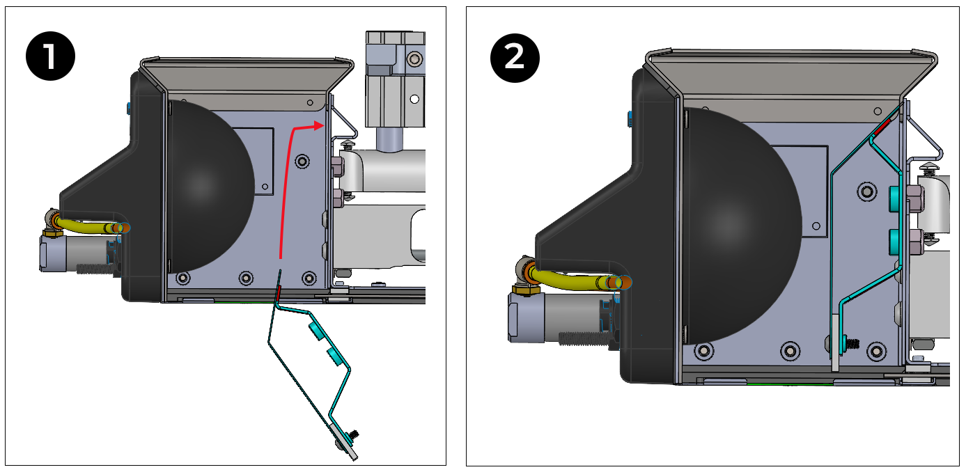
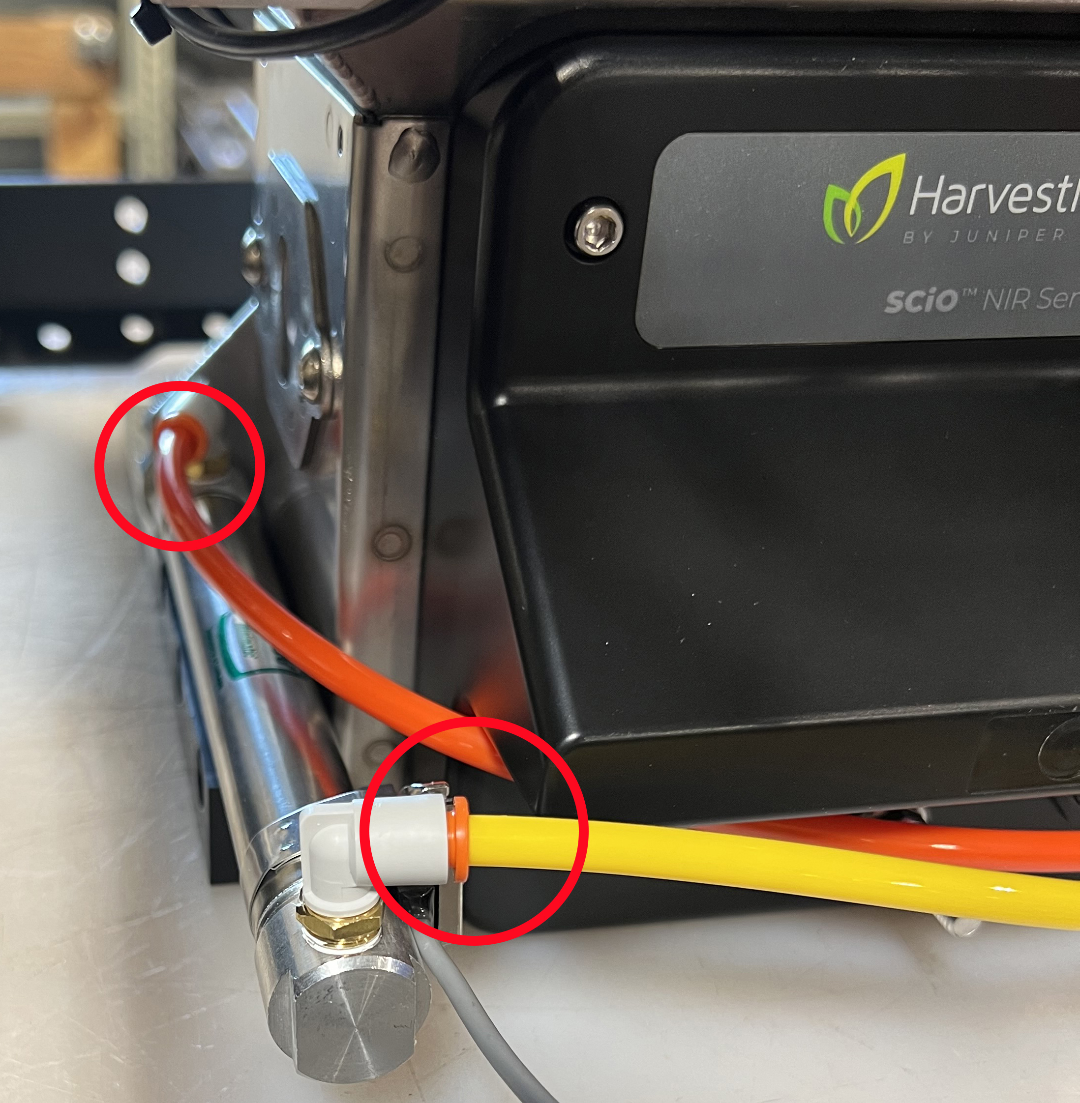
- Disconnect the orange and yellow air hoses from the left of the cylinder to give access to the SCiO Sensor mounting area.
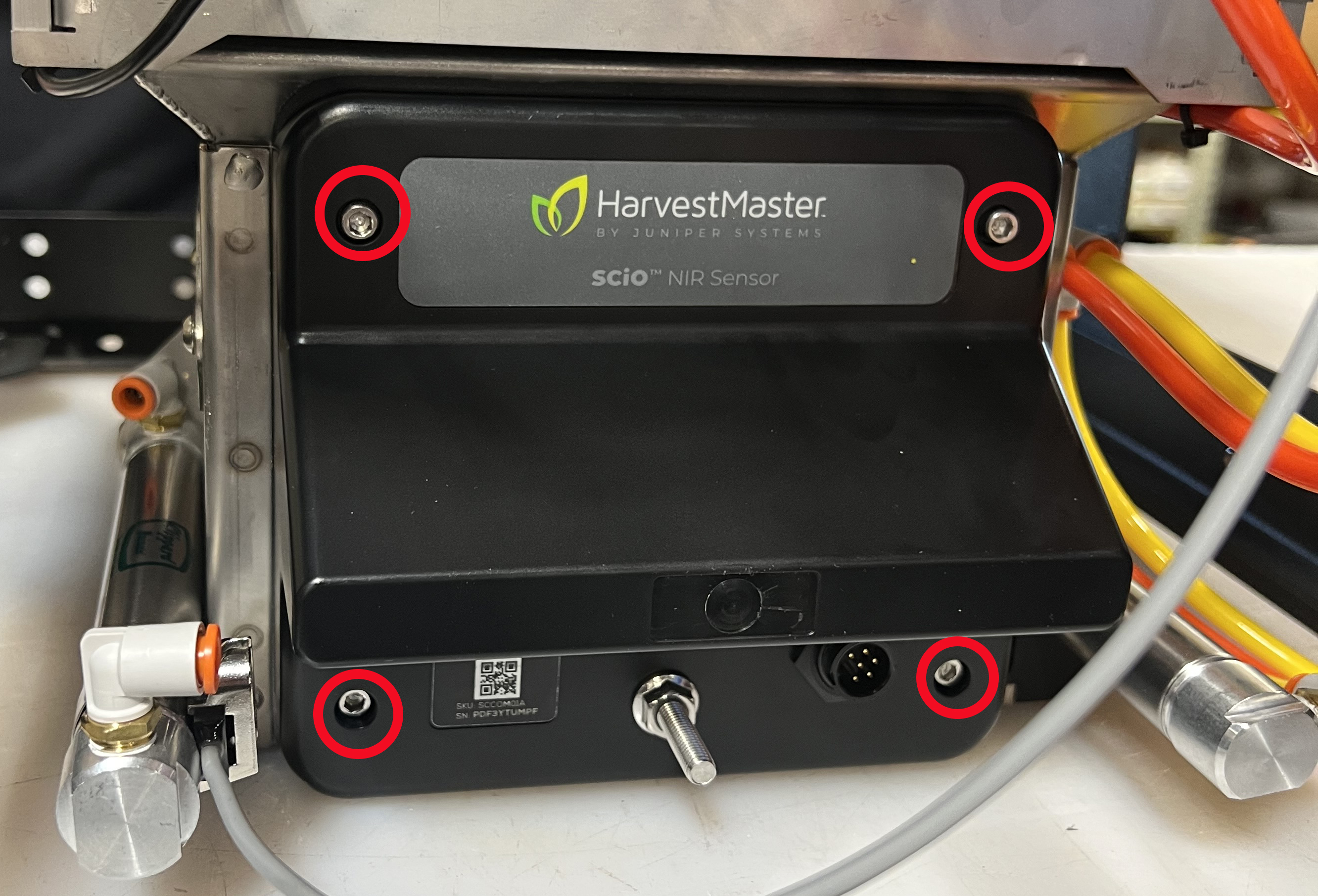
- Remove the four 8-32 x 3/16 SS button socket head cap screws securing the H3 SCiO hole plug plate (PN 31740) to the test chamber. Save the plug plate and screws for future installation.
- Position the SCiO Sensor in the test chamber. For best results,
- Match the top of the sensor to the top of the chamber opening.
- Insert the sensor at a slight angle with the top of the sensor angled toward the opening.
- Tighten the four captive screws in the sensor, using a cross pattern.
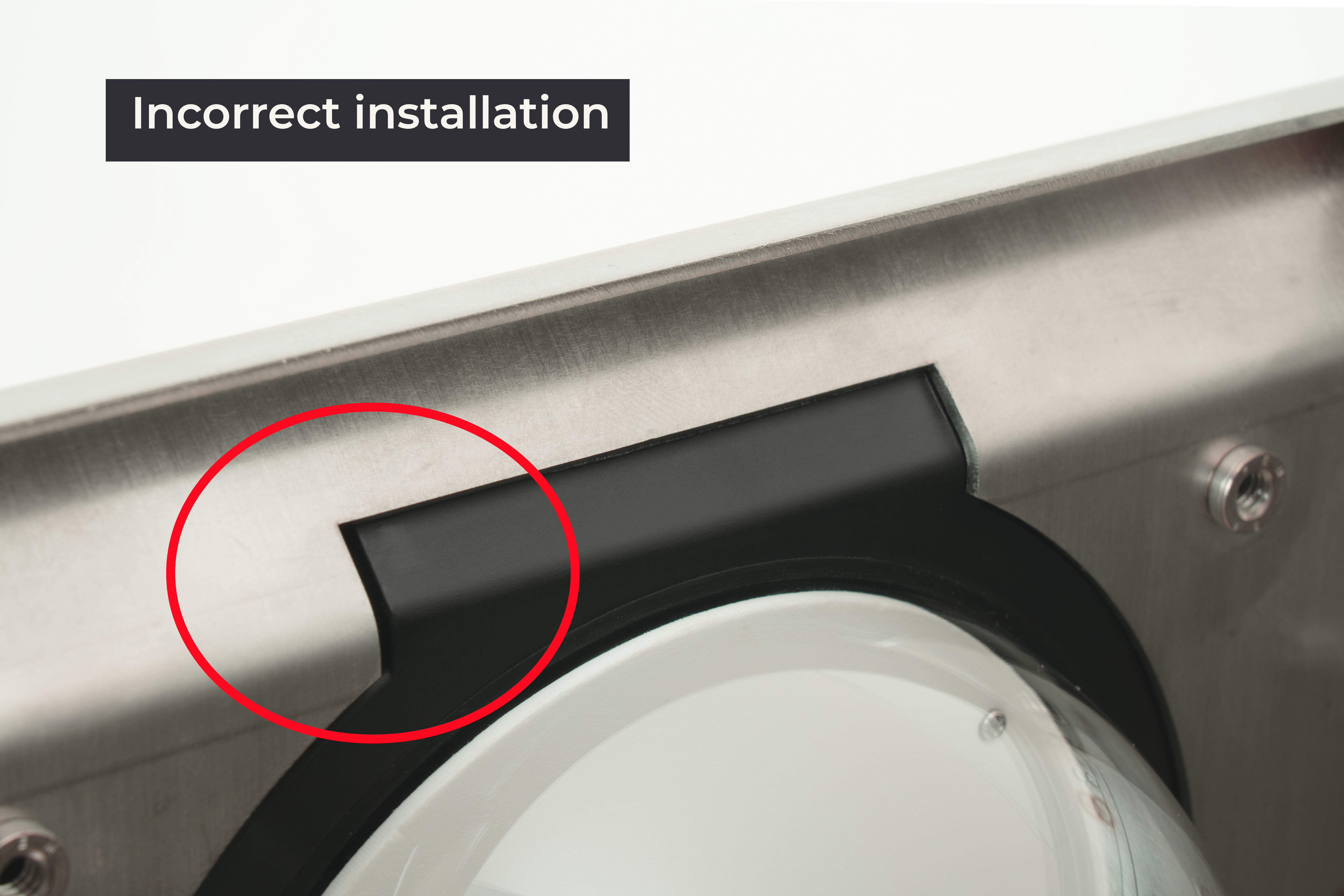
CAUTION: The screws will still tighten even when misaligned, and it's not always obvious. If the sensor plastic is recessed or misaligned, loosen the four screws and realign.
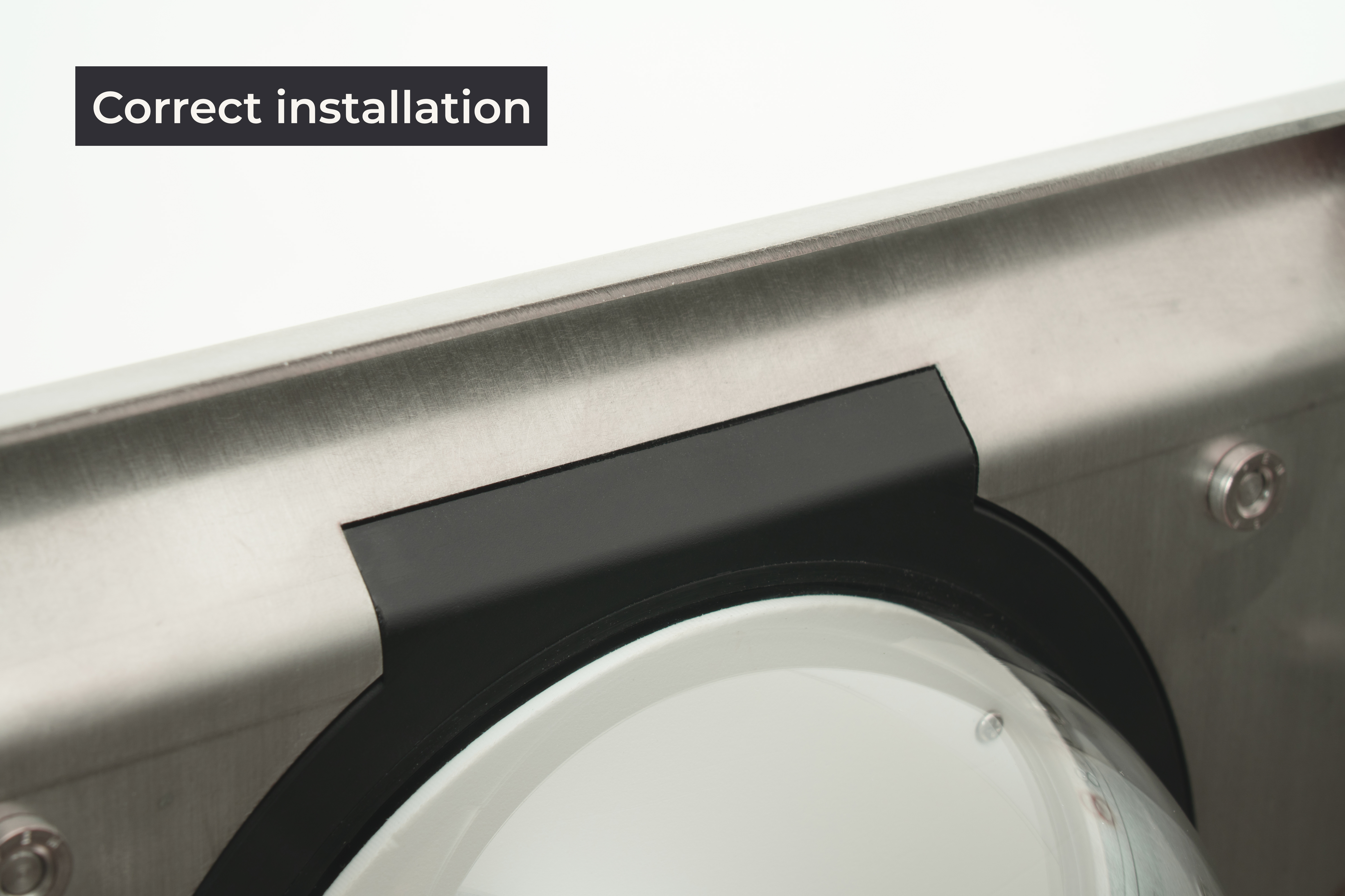
- Ensure the SCiO Sensor aligns properly with the test chamber from the inside.
In proper alignment,- The square portion of the sensor inserts fully through the sheet metal.
-
The sensor plastic is flush with the inside of the sheet metal. It is not recessed. There is no gap.
- Connect the air lines to the left of the air cylinder.
- Attach the SCiO cable assembly (PN 30712) to the outside of the GrainGage, using the 1/4‒20x1/2 in. socket head cap screw and nylock nut.
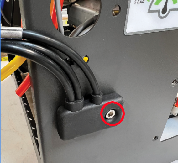
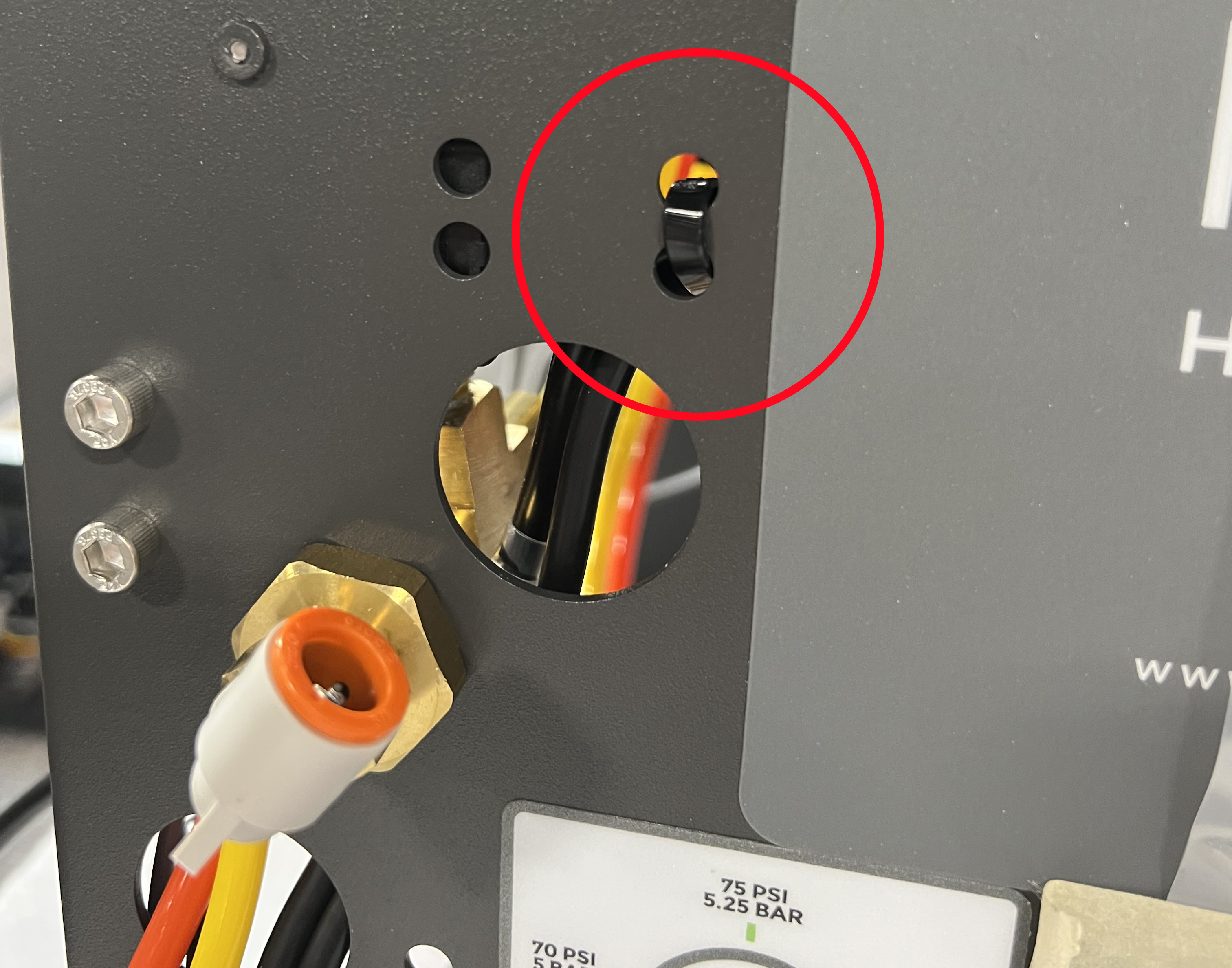
- Thread the cables through the hole in the chassis.
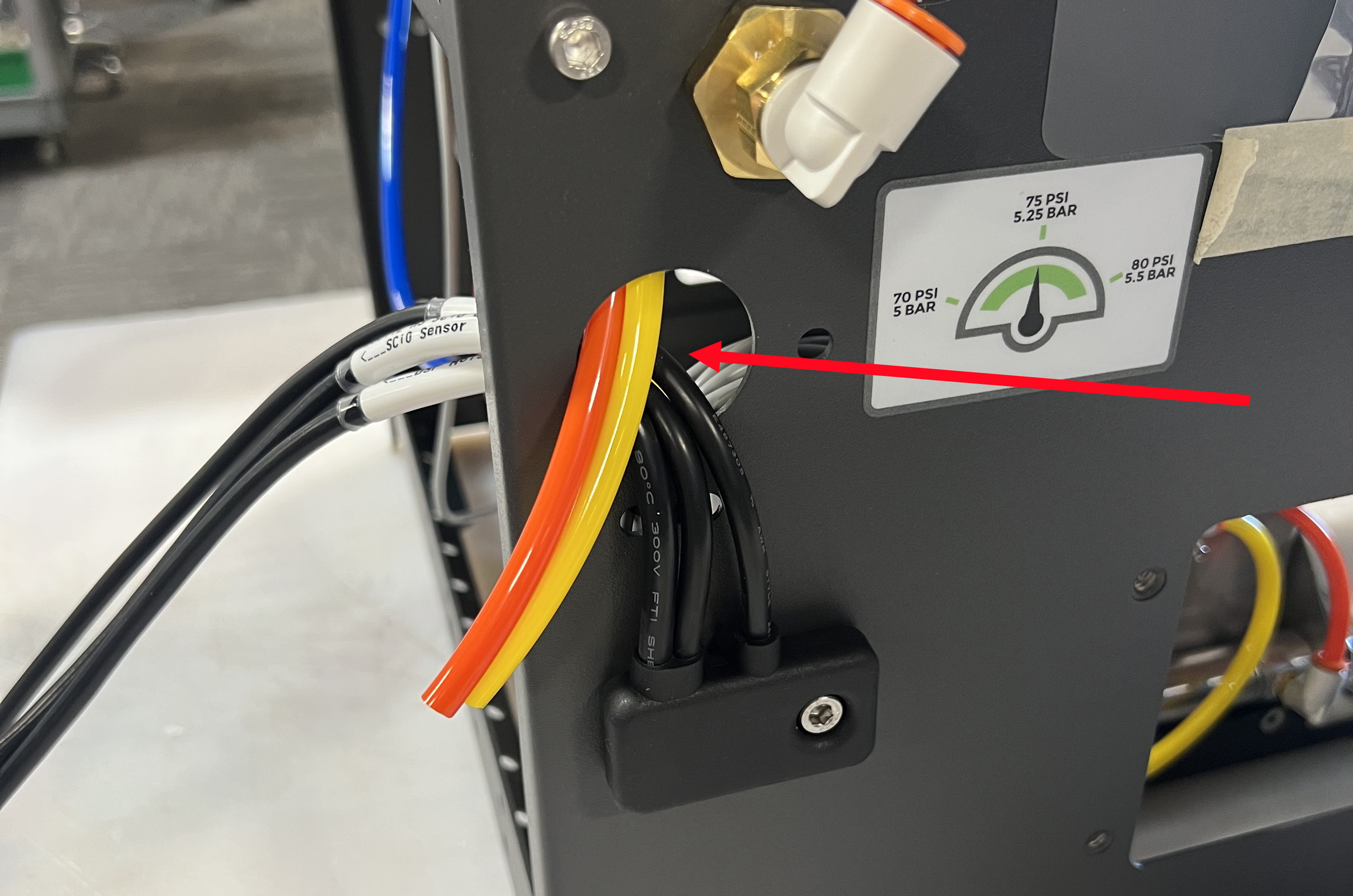
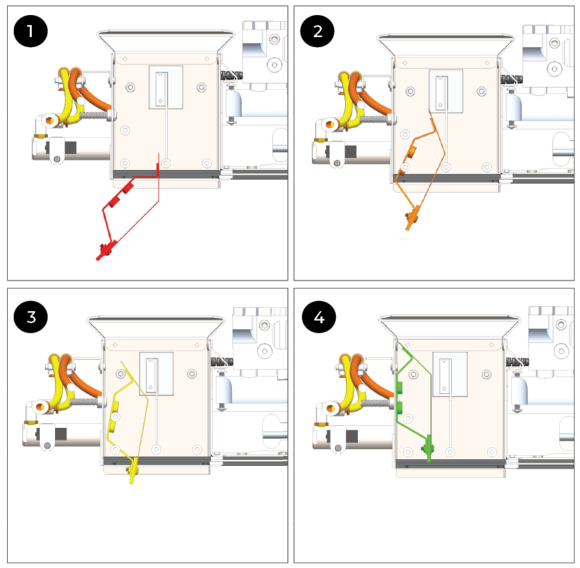
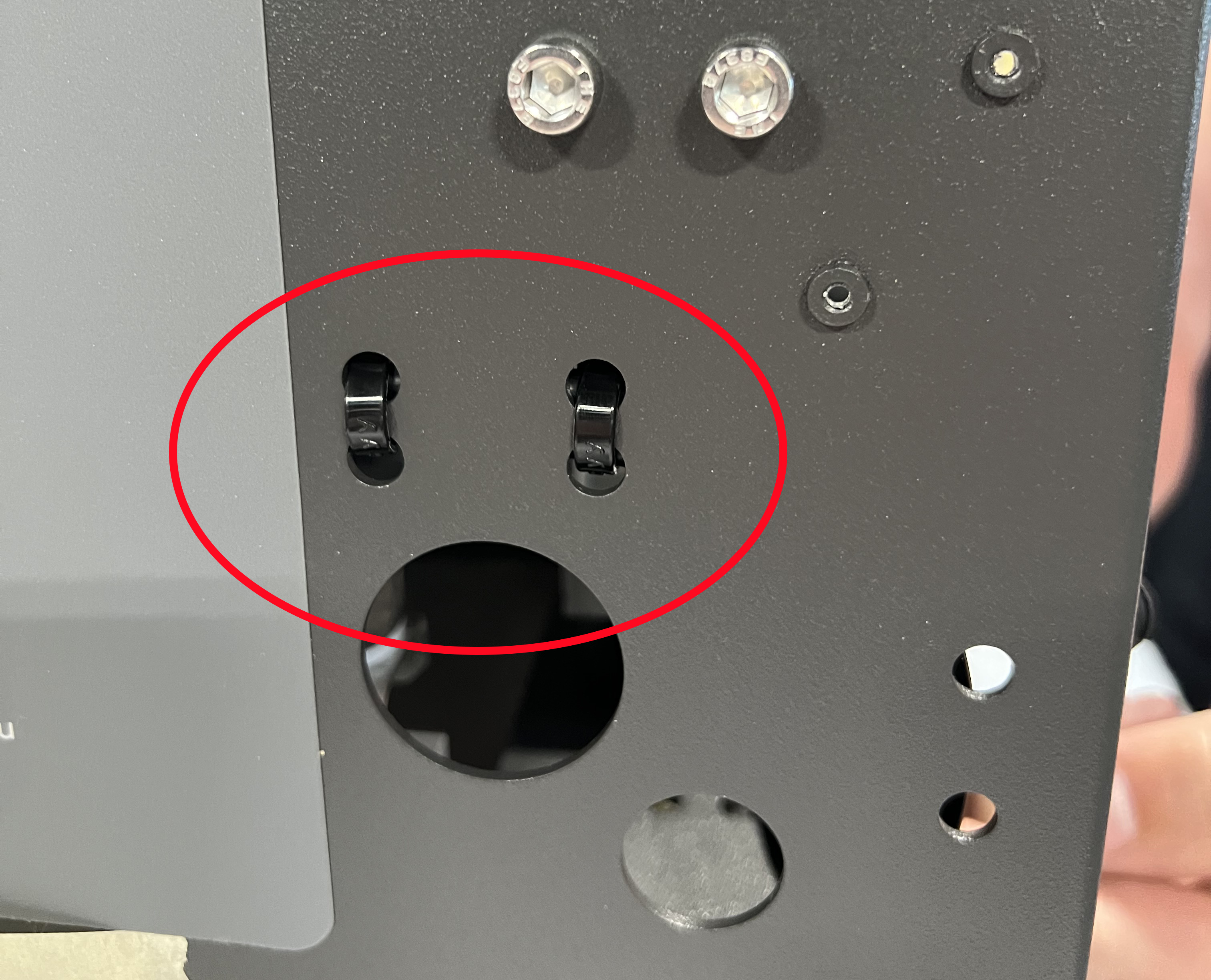
- Route the computer and DSP moisture cables toward the DSP side of the GrainGage along the inside wall of the chassis. Use the cable routing tabs.
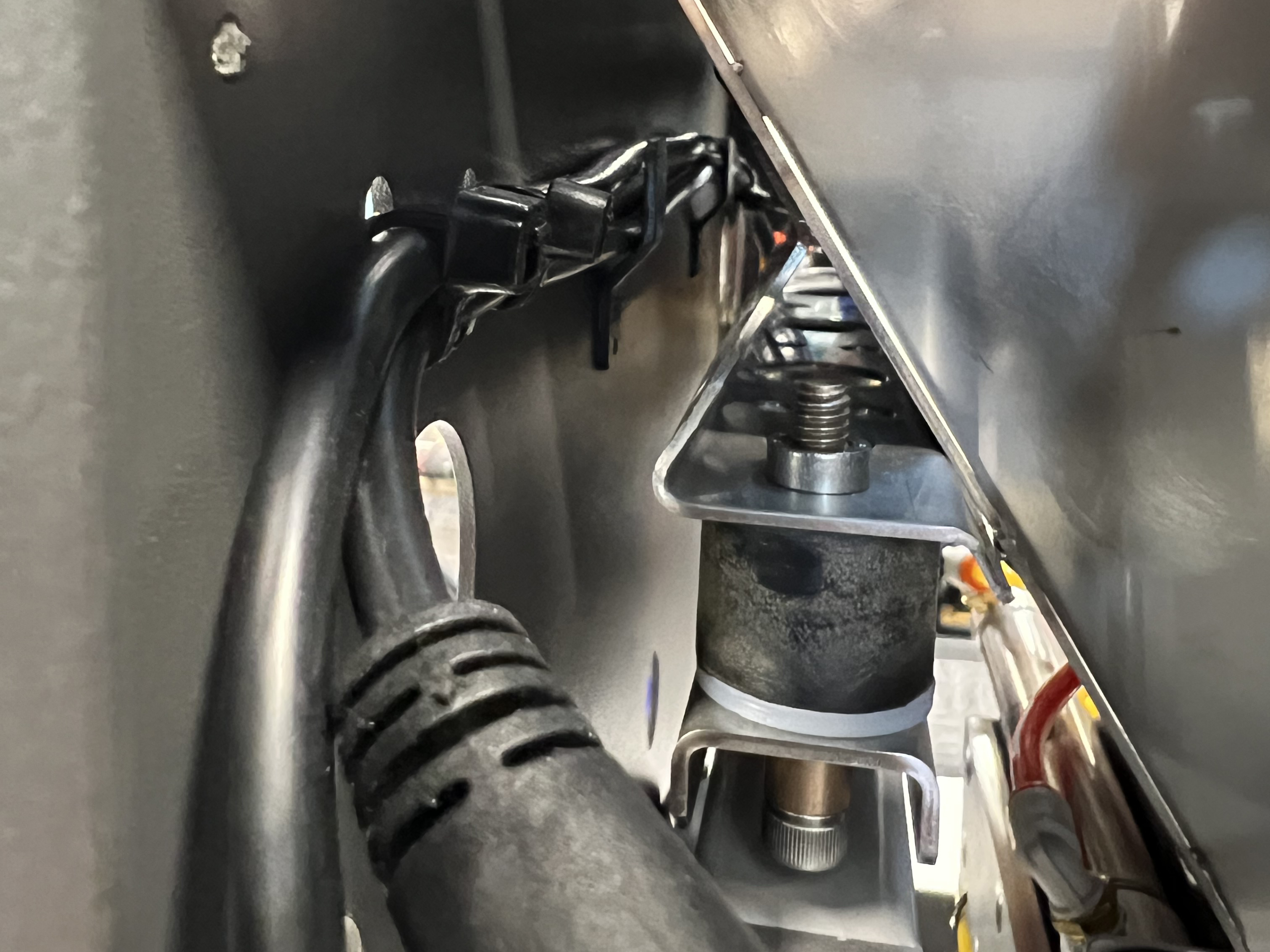
- Use a zip tie to secure the cables to the chassis, as shown.
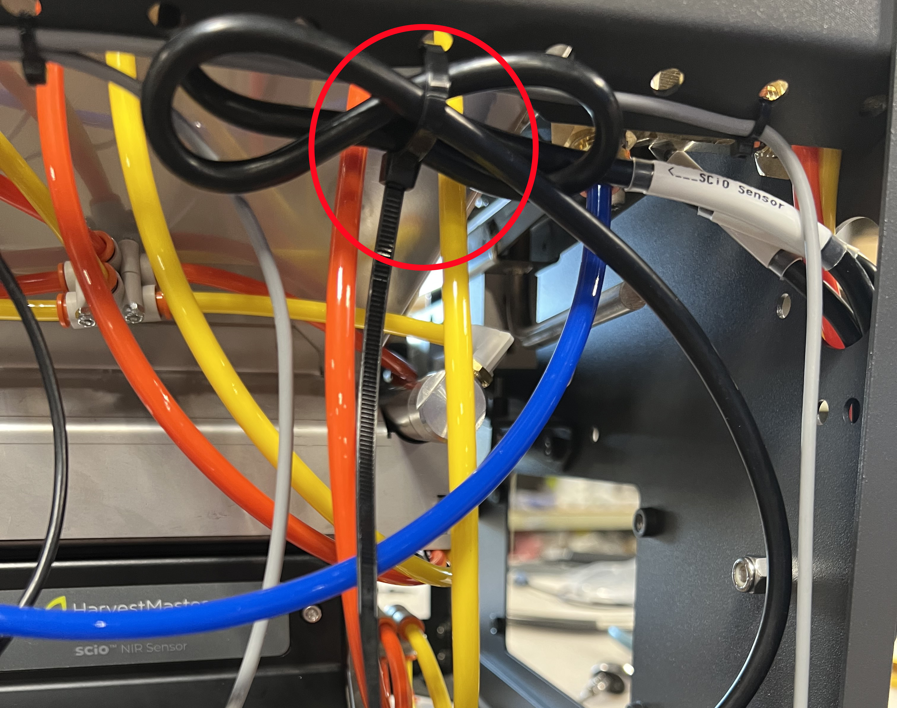
- Secure the moisture cable to the crossbar with zip ties, as shown.
- Attach the moisture cable to the DSP moisture port.
- Connect the SCiO Sensor cable to the end of the SCiO Sensor.
- Loop and secure the extra length of SCiO cable to the chassis crossbar.
Note: Leave enough slack in the cable that it will not touch the side of the chassis as the chamber moves. The looped cable can be secured under the crossbar or tucked inside the crossbar. - If not installed, attach the H3 moisture sensor plug plate (PN 31796) to the exterior of the test chamber with two 8-32 x 3/16 SS button head socket head cap screws.
Remove the SCiO Sensor
To remove the SCiO Sensor,
- Disconnect the SCiO Sensor cable from the end of the SCiO Sensor.
- Disconnect the moisture cable from the DSP moisture point.
Note: If you will be reinstalling the SCiO Sensor at a later time, leave the SCiO moisture and computer cables routed along the chassis crossbar. Add zip ties as needed to hold the SCiO cables away from the weigh bucket and any moving components.
- (Optional) Remove the zip ties securing the moisture cable to the crossbar.
- (Optional) Remove the zip tie securing the DSP moisture and computer cables.
- (Optional) Unscrew the 1/4‒20x1/2 in. socket head cap screw and nylock nut that attaches the SCiO cable assembly to the outside of the GrainGage.
- Disconnect the air lines to the left of the air cylinder.
- Remove the four captive screws in the SCiO Sensor.
- Remove the SCiO Sensor from the test chamber.
- Cover the SCiO Sensor hole with the H3 SCiO hole plug plate (PN 31740). Attach it to the exterior of the test chamber with four 8-32 x 3/16 SS button head socket head cap screws.